background image

INSTRUCTIONS MANUAL

004AZ011B

VISION SYSTEM FOR AUTOMATIC INSPECTION OF 

CAPS

CVS

T E C H N I C A L
D O C U M E N T A T I O N

ENGLISH

Original Instructions

Summary of Contents for CVS Series

Page 1: ...INSTRUCTIONS MANUAL 004AZ011B VISION SYSTEM FOR AUTOMATIC INSPECTION OF CAPS CVS T E C H N I C A L D O C U M E N T A T I O N ENGLISH Original Instructions...

Page 2: ......

Page 3: ...MANUAL VISION SYSTEM FOR AUTOMATIC INSPECTION OF CAPS CVS MANUFACTURER S C Via Selice Provinciale 17 A 40026 IMOLA Bologna ITALY www sacmi com RELEASE DATE 21 12 2015 21 09 2017 VERSIONS CVS001 CVS05...

Page 4: ...004AZ011B...

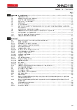
Page 5: ...1 3 PCI S32P I O board 2 4 2 1 1 4 Image capture card 2 6 2 1 1 4 1 Type D E F image capture card 2 6 2 1 1 5 Additional electrical cabinet 2 7 2 1 1 6 Image shooting station 2 8 2 1 1 6 1 Cameras and...

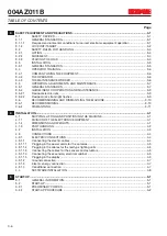
Page 6: ...ISSIONING AND DISMANTLING THE MACHINE 3 10 3 6 1 DECOMMISSIONING 3 10 3 6 2 DISMANTLING 3 11 4 INSTALLATION 4 1 4 1 SHIPPING LIFTING AND POSITIONING THE MACHINE 4 1 4 1 1 DIVISION OF THE ELECTRONIC EQ...

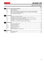
Page 7: ...OR CHECKING THE CAPTURE AND EJECTION DEVICES 7 1 7 1 1 1 Adjusting the front back image shooting station 7 1 7 1 2 PROCEDURE FOR CHECKING THE CAPTURE AND EJECTION MECHANISM 7 2 7 1 3 PROCEDURE FOR CHE...

Page 8: ...004AZ011B TABLE OF CONTENTS Page 0 8...

Page 9: ...SACMI reserves the right to make technical changes to the electronic equipment and this manual without giving prior notice Additional copies of this manual can be obtained by contacting SACMI s Custom...

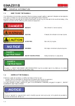
Page 10: ...NING Warnings not related to physical injuries D0003276_00 SAFETY INSTRUCTIONS SAFETY INSTRUCTIONS Safety instructions or procedures D0003276_00 SAFETY INSTRUCTIONS Chapter 3 SAFETY EQUIPMENT AND PREC...

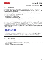
Page 11: ...r malfunctioning of other equipment connected to the electronic equipment The warranty covers only electronic equipment damage and or malfunctions with explicit exclusion of compensation for any addit...

Page 12: ...must be effectively grounded E0038 Lift point E0167 Instructions manual must be read OTHER SIGNS E0168 When discarding electric and electronic equipment separate them to permit correct recycling and p...

Page 13: ...004AZ011B GENERAL INFORMATION 1 1 5 1 8 POSITION OF THE SAFETY SIGNS D0003275_00 NOTICE The type of signs may vary in relation to the laws in force in the country the equipment is installed in...

Page 14: ...MATION 1 6 1 9 IDENTIFICATION PLATE FOR THE ELECTRONIC EQUIPMENT If the electronic equipment is equipped with good sized cameras identification plates are provided on them The serial number stamped on...

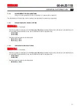
Page 15: ...indicated below the references to standards are to be considered extended also to the next amendments and or supplements 2014 30 EU 2014 35 EU that the equipment also meets standards EN 61010_1 2011...

Page 16: ...004AZ011B 1 GENERAL INFORMATION 1 8...

Page 17: ...c and or metal caps by means of an image capture system The electronic equipment in particular the mechanical and electronic parts that make it up is dealt with in this chapter A CVS system may have o...

Page 18: ...ditions Further information regarding the air conditioner is given in the enclosed documentation as indicated in chapter 1 GENERAL INFORMATION paragraph ATTACHMENTS An uninterrupted power supply 2 ens...

Page 19: ...bles Image capture card IP1 is inserted in the other slots not indicated in the figure The number and model provided is strictly related to the vision system version In addition to the Personal Comput...

Page 20: ...ge capture cards for trigger strobe 64 auxiliary 5 V digital inputs outputs In addition the operating logic of the board is determined by a program residing in the flash memory that is transfered insi...

Page 21: ...r 3 Status leds 4 Auxiliary signal connectors 5 EPLD Acex programmable logic 6 Flash 7 Board programming connector Leds DGB0 DGB1 and DGB2 depend on the logic DGB1 indicates the state of the optoisola...

Page 22: ...RAL INFORMATION paragraph ATTACHMENTS The main specifications of the image capture card used are indicated below 2 1 1 4 1 Type D E F image capture card Type D E F image capture cards are half size PC...

Page 23: ...in the cabinet A card set up to control 6 lighting units 2 ejectors 5 inputs sensors encoders and a status indicator tower Terminal block XT1 1 that joins the card to the accessories Terminal block X...

Page 24: ...1 GENERAL INFORMATION paragraph ATTACHMENTS In addition we would like to underline that a single electrical cabinet can control several image shooting stations installed in the same production line T...

Page 25: ...obtain the best light In LED lights either white or red LEDs are used to light up objects The diffused light is used to reduce reflections however it tends to hide defects like abrasions scratches an...

Page 26: ...ORMATION paragraph ATTACHMENTS 2 1 1 7 2 Ejection stations A solenoid valve is used to eject defective pieces This valve can either control pneumatic pistons or directly work on the pieces by means of...

Page 27: ...nufacturer SACMI will not be held responsible for any personal injury equipment damage or malfunctions caused by use manners different from those specified in this manual MISUSE OR ERRONEOUS USE SACMI...

Page 28: ...OVERALL DIMENSIONS 1 Personal computer UPS 2 Image shooting station the dimensions vary according to how it is installed 3 Electrical cabinet optional 2 2 OVERALL DIMENSIONS The approximate dimensions...

Page 29: ...ion class II Specifications of the industrial grade Personal Computer Processor Intel core I7 2600 3 40 GHz 8 MB CACHE or more RAM 2 x 4 GB DDR3 MHz or more Hard disk SATA 2 x 500 GB or more SSD 2 x 1...

Page 30: ...W A fn Hz Un V IP O d V Order No E0004 E0159 S A C M I I M O L A S C V I A S E L I C E P R O V I N C I A L E 1 7 A I M O L A I TA L I A 004AZ011B 2 FEATURES 2 14 2 3 2 ACCEPTABLE FLUCTUATIONS ELECTRI...

Page 31: ...nctional block diagrams are given in this chapter They are supplied to aid in the description of the devices See also the attached wiring diagram of the main electrical cabinet as indicated in chapter...

Page 32: ...fed by a constant voltage of 48 V whereas the pulse length is set by means of the board SMC_I O The IP image capture card sends a pulse to the MONO block and the output of the MONO block enters a COMP...

Page 33: ...cessary a signal is sent to the solenoid valve to eject the product if judged defective The position of the camera s and ejector s in relation to the sensor can be changed They can be set by the user...

Page 34: ...vision system can identify several types of defects regarding the aesthetic and or mechanical quality of plastic and or metal caps like visible overflow visible spots deformations ovalization off cen...

Page 35: ...t meet standard In particular it must be free of shadows bothersome glaring and stroboscopic effects Some environmental conditions such as sea level high relative humidity and high temperatures may af...

Page 36: ...n the OFF or O position with a LockOut multiple device Remove the keys to the locks and personally hold on to them D0003273_00 WARNING D0000004_00 As there are a number of drive and or electronic conv...

Page 37: ...T6912 SAFETY EQUIPMENT AND PRECAUTIONS 3 3 3 004AZ011B FIGURE 3 1 2 LOCKOUT TAGOUT QS1...

Page 38: ...e sure all personnel is safely away and that no one can enter the area where the machine is being moved make sure the load is stable gradually lift in a vertical manner in order to avoid swaying and i...

Page 39: ...les clean dry and well lit The customer must make sure that fire suppressors are provided in the area where the electronic equipment is installed and that there is a system for protection against volt...

Page 40: ...at least understand the technology employed and have specific experience in operating this type of electronic equipment be well educated and able to read and fully understand the contents of this manu...

Page 41: ...ic equipment performance and proper and safe operation routine maintenance must be performed at the intervals and in the modes specified by SACMI In particular regularly check all the safety devices f...

Page 42: ...ny nameplates and stickers provided on the electronic equipment The user must restore the markings conductors terminals devices etc monitor signals and nameplates when no longer legible or if removed...

Page 43: ...ven when the main switch is in position OFF and or the cabinet is open due to malfunctions the UPS if provided continues feeding the Personal Computer 3 5 2 2 Residual risks from light flashes D000327...

Page 44: ...d personnel properly trained on how to work on and handle the electronic equipment are authorized to work on it Use only adequate lift means and equipment that comply with current regulations and stan...

Page 45: ...STRUCTIONS Disassemble the electronic equipment observing current safety standards and following the instructions given in chapter 4 INSTALLATION and safety guidelines given in paragraphs SAFETY RULES...

Page 46: ...3 SAFETY EQUIPMENT AND PRECAUTIONS 3 12 004AZ011B...

Page 47: ...l cabinet optional 4 Support optional 4 INSTALLATION 4 1 SHIPPING LIFTING AND POSITIONING THE MACHINE 4 1 1 DIVISION OF THE ELECTRONIC EQUIPMENT The electronic equipment is divided into various blocks...

Page 48: ...ing the smaller parts and packages be careful and use the most suitable equipment observing the safety precautions D0003276_00 SAFETY INSTRUCTIONS Only specially trained authorized personnel may lift...

Page 49: ...nd display console and put it in the required position Position the image shooting stations and connect them to the conveyor system according to the arrangements made for personalizing the system The...

Page 50: ...3275_00 NOTICE The various electronic parts can be connected and hooked up to the mains only by specialized personnel instructed by SACMI D0003276_00 SAFETY INSTRUCTIONS As there are a number of elect...

Page 51: ...g station and fit it into the connector of the lighting unit 4 4 3 1 1 3 Connecting the cables for the sensors and actuators Connect the cables in the image shooting sensors of the encoder and of the...

Page 52: ...UPS T6785 4 INSTALLATION 4 6 004AZ011B FIGURE 4 3 1 1 CONNECTING THE ELECTRIC CABLES 1 3 2 4 CAMERA LINK...

Page 53: ...s section are adequate for the electrical wiring to the device marked in the main electrical cabinet generally speaking the power cables are connected to the master switch in the main electrical cabin...

Page 54: ...ety measure in the event that data is canceled files are damaged or the hard disk goes down Keep these disks in a safe place In any case several CD ROMs are supplied with this manual These allow the s...

Page 55: ...talled in the electronic equipment are used spare parts are incorrectly installed jobs or modifications not authorized by SACMI are carried out the machine is tampered or altered in any way The custom...

Page 56: ...o capture the images 6 After being sure that the configuration is efficient adjust the guides and presence sensor Capture images of moving pieces using the synchronized capture command 7 Once the corr...

Page 57: ...rror messages appear Set the system to inspection mode 6 1 2 START UP WITH MODIFICATIONS MADE TO THE SOFTWARE CONFIGURATION Start up with modifications made to the software configuration implies that...

Page 58: ...rations are correct and that no warning and or error messages appear Create the required configuration Place a product to be inspected in front of the image shooting station Operate the asynchronized...

Page 59: ...ace Press the Test button to see if the reject device works in a trouble free manner Set the system to operate with the synchronized capture and allow the products to travel Select the various ejectio...

Page 60: ...rom the conveyor belt Use two empty containers one for defective products and the other for good quality ones to collect the products being inspected on the conveyor Mix together the defective product...

Page 61: ...other for good quality ones to collect the products on the conveyor 4 Mix together the prepared defective samples and good quality ones and feed them to the vision system The normal operating speed an...

Page 62: ...7 ADJUSTMENTS 7 4 004AZ011B...

Page 63: ...tart up isolate all the power supplies electrical air etc with personal devices for example pad locks stamped with the name of the operator who put it on remove the keys to the locks and personally ho...

Page 64: ...electronic equipment off Use only specially formulated products to clean the screen D0003275_00 NOTICE Do not use solvents 8 1 SCHEDULED MAINTENANCE 8 1 1 ROUTINE MAINTENANCE Unit and intervention po...

Page 65: ...MAINTENANCE OPERATIONS Special training is required to perform special maintenance work which may therefore be carried only by the manufacturer s expert personnel For this reason these types of opera...

Page 66: ...8 MAINTENANCE 8 4 004AZ011B...

Page 67: ...abinet doors to prevent damage from tampering and dust from getting in 9 DISMANTLING 9 1 DECOMMISSIONING D0003276_00 SAFETY INSTRUCTIONS Only skilled personnel properly trained on how to work on and h...

Page 68: ...ions and standards D0003273_00 WARNING Disassemble the electronic equipment observing current safety standards and following the instructions given in chapter 4 INSTALLATION and safety guidelines give...

Reviews: