background image

Air Cooled Mini Chiller

Models: F

VCA 40-200 B(R), 50-80 C(R)  


Ref, S-  080 / 05 / 12

    Sakura Air Conditioner

User-friendly, Earth-friendly

Summary of Contents for FVCA-40 B

Page 1: ...Air Cooled Mini Chiller Models FVCA 40 200 B R 50 80 C R Ref S 080 05 12 Sakura Air Conditioner User friendly Earth friendly...

Page 2: ...4 General Data 4 Operating Range 6 System Schematic Diagram 7 Controller Features and Algorithm 10 Sound Data 13 Equipment Selection 15 Dimensions 2 Wiring Diagrams 2 Installation 3 Servicing and Main...

Page 3: ...Page 2 Product Nomenclature Air Cooled Mini Chiller FVCA 50 C R R Heatpump If omitted indicates cooling only C Product Generation FVCA Package Side Air Discharge 50 Unit Size...

Page 4: ...gh Discharge temperature protection compressor overload protection high low pressure switch lter drier anti freeze protection and automatic manual defrost functions distinguish chillers with its outst...

Page 5: ...idth mm Height mm kg Model Nominal Input Power Running Current Power Source Nominal Cooling Capacity Nominal Heating Capacity Available Head Water Pipe Connection Unit Weight Unit Dimension Sound Pres...

Page 6: ...ing A 22 2 27 6 32 5 V Ph Hz kg 4 0 x 2 5 0 x 2 5 4 x 2 m 3 h 5 4 6 9 8 6 kW 0 7 1 1 meter H2O 15 18 18 dBA 65 69 69 DN 40 Length mm Width mm Height mm Length mm Width mm Height mm kg 390 470 550 Mode...

Page 7: ...eating 16 35 46 Outdoor ambient temperature CDB 0 10 Leaving water temperature C 7 15 40 7 5 STD 25 55 45 35 7 7 Leaving water temperature C STD Outdoor ambient temperature CDB STD Without glycol solu...

Page 8: ...ATER OUT WATER PUMP CAP TUBE PLATE HEAT EXCHANGER COMPENSATION TANK COMPRESSOR FIN TUBE HEAT EXCHANGER COOLING OPERATION P WATER PUMP WATER IN WATER OUT COMPENSATION TANK PLATE HEAT EXCHANGER CAP TUBE...

Page 9: ...P TUBE LIQUID RECEIVER COMPENSATION TANK LIQUID RECEIVER COMPRESSOR FIN TUBE HEAT EXCHANGER COOLING OPERATION P FIN TUBE HEAT EXCHANGER 4 WAY VALVE COMPRESSOR CAP TUBE COMPENSATION TANK WATER IN WATER...

Page 10: ...MPRESSOR FIN TUBE HEAT EXCHANGER PLATE HEAT EXCHANGER COOLING OPERATION P COMPRESSOR 4 WA Y VALVE CHECK VALVE ACCUMULATOR FIN TUBE HEAT EXCHANGER LIQ UID RECEIVER FILTER D RIER TXV COMPRESSOR TXV FILT...

Page 11: ...mode c Water Temperature Display In standard operating condition the wired controller will display OUT to indicate leaving water temperature display To change the water temperature display press and...

Page 12: ...key simultaneously for 5 sec will enter manual defrost mode There is a long BEEP sound to indicate manual defrost g Key Lock To prevent unauthorized and accidental setting of control the system comes...

Page 13: ...nal alarm_in water pump overload EN SAVE contact open 8 Flow switch open Flow switch open 9 Condenser 1 high temperature Condenser 1 temperature 65 C 10 11 Condenser 1 temperature sensor error Condens...

Page 14: ...ound Pressure Test Setup Outdoor Unit Sound Data MICROPHONE AIR DISCHARGE 1m 1m Test standard JB T 4330 1999 Indoor Unit 1 4 m Mini Chiller 1 4 m below the mini chiller MICROPHONE Test standard GB T 1...

Page 15: ...61 56 53 69 59 FVCA 200 B R 68 64 66 65 61 56 53 69 59 Model 1 1 Octave Sound Pressure Level dB ref 20 Pa Overall dBA Noise Criteria FVCA 80 B R 125 Hz 250 Hz 500 Hz 1 kHz 2 kHz 4 kHz 8 kHz FVCA 50 C...

Page 16: ...IIHUHQFH By knowing the above data the suitable unit can be selected though System Performance table The water pressure drop can be found in the Pump Curve For glycol application correct the capacity...

Page 17: ...83 8 49 28 87 9 09 31 73 9 17 27 38 10 20 25 00 11 12 23 78 11 46 6 32 10 8 57 30 90 9 12 32 76 9 36 29 11 10 28 26 61 11 16 25 29 11 54 7 34 36 8 61 32 99 9 21 33 79 9 51 31 50 10 40 28 22 11 24 26...

Page 18: ...ine capacity and pressure drop for a FVCA40C with 10 glycol solution Entering water temperature is 10 C leaving water temperature is 5 C Ambient temperature is 30 C 1 For the System Performance Table...

Page 19: ...th 10 glycol solution by multiplying performance with correction factor Capacity 20 15 x 0 959 19 32 kW DWHU RZ P K Pressure drop 3 1 x 1 06 3 29 kPa Glycol Water Flow Pressure Drop 10 1 02 1 06 20 1...

Page 20: ...67 24 89 6 06 23 44 6 48 22 50 6 80 21 02 7 39 19 92 7 64 5 25 57 7 18 24 75 7 69 27 20 7 76 23 47 8 63 21 42 9 41 20 38 9 70 6 27 51 7 25 26 49 7 72 28 08 7 92 24 95 8 70 22 81 9 44 21 68 9 76 7 29 4...

Page 21: ...9 36 42 8 86 41 26 9 20 45 17 39 8 25 18 79 8 35 22 70 8 65 26 05 8 93 30 00 9 20 33 12 9 48 34 70 9 57 39 49 9 95 50 15 39 8 76 16 84 8 86 20 74 9 23 24 19 9 51 28 28 9 78 31 39 10 19 33 02 10 29 37...

Page 22: ...R C R 0 5 10 15 20 25 30 0 0 4 0 8 1 2 1 6 2 2 4 2 8 3 2 3 6 Water Flow Rate m 3 h Pressure Head m 1 5 3 4 System Head Pump Head 0 5 10 15 20 25 30 0 0 4 0 8 1 2 1 6 2 2 4 2 8 3 2 3 6 Water Flow Rate...

Page 23: ...Pump Curve FVCA 100 B R 0 5 10 15 20 25 30 0 1 2 3 4 5 6 7 8 Water Flow Rate m3 h Pressure Head m 2 3 5 3 Pump Head System Head 0 5 10 15 20 25 30 0 1 2 3 4 5 6 7 8 Water Flow Rate m 3 h Pressure Hea...

Page 24: ...e FVCA 150 B R 0 5 10 15 20 25 30 0 1 2 3 4 5 6 7 8 Water Flow Rate m 3 h Pressure Head m 3 6 7 2 Pump Head System Head 0 5 10 15 20 25 30 35 40 45 0 1 2 3 4 5 6 7 8 9 10 11 Water Flow Rate m3 h Press...

Page 25: ...Page 2 Pump Curve FVCA 200 B R 0 5 10 15 20 25 30 35 40 45 0 1 2 3 4 5 6 7 8 9 10 11 Water Flow Rate m3 h Pressure Head m 5 6 9 9 System Head Pump Head...

Page 26: ...872 0 779 1 0 925 0 924 0 891 0 795 2 0 951 0 941 0 911 0 813 5 0 959 0 952 0 921 0 825 7 0 963 0 957 0 924 0 825 10 0 962 0 957 0 926 0 828 Capacity Glycol Leaving Water Temperature C Glycol Water F...

Page 27: ...Page 2 Dimensions Dimension in mm Model FVCA 50C R 60B R Model FVCA 40B Dimension in mm...

Page 28: ...Page 2 Model FVCA 150 200 B R Dimension in mm Dimension in mm Model FVCA 80 C R 80 100 120 B R...

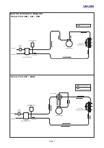
Page 29: ...Page 2 Wiring Diagram Wiring Diagrams Model FVCA 40B...

Page 30: ...Page 2 Wiring Diagram Model FVCA 50C Model FVCA 50CR...

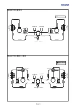
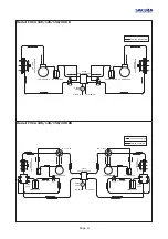
Page 31: ...Page Model FVCA 60B Model FVCA 60BR...

Page 32: ...Page Model FVCA 80 C Model FVCA 80 CR...

Page 33: ...Page 3 Model FVCA 80 100 120 B Model FVCA 80 100 120 BR...

Page 34: ...Page 3 Model FVCA 150 200 B Model FVCA 150 200 BR...

Page 35: ...ensure a gradient is maintained as shown in the following diagrams Ropes Support Protection Outdoor Unit Installation 7KH FKLOOHU PXVW EH SODFHG RQ D ULJLG DQG VROLG VXUIDFH H J FRQFUHWH RRU PHWDO EU...

Page 36: ...the system is free of dust and moisture Note Vacuum level must be maintained at 130Pa for at least 5 minutes to check for leakage Water Piping a Air vent must be installed at the highest position Ope...

Page 37: ...chiller Expansion tank No Details Model FVCA Water pipe diameter Pipe dimension must be properly selected to keep low noise level and water friction Refer to the table below for recommend water pipe...

Page 38: ...pacity kW 8 10 3 Note The data above is RECOMMENDED heater capacity The auxiliary heater is not provided by factory Refer to the following diagrDP IRU DX LOLDU KHDWHU LQVWDOODWLRQ Note a During commis...

Page 39: ...OO LQ FOHDQ ZDWHU DQG FKHFN SURSHUO HWV the unit warm up 6 hours before ON the unit to ensure the unit is in good condition 7 Check the working pressure regularly to ensure no gas is leaking When gas...

Page 40: ...cient refrigerant Low water flow Condenser coil blocked dirty Wrong TXV setting Strainer choked Low refrigerant flow Water system choked air trap Refrigerant over charged Ambient temperauture too high...

Page 41: ...o N n o Description 1 EXV 9 Rear Service Panel 2 PWM Valve 10 Front Panel 3 Low Pressure Switch 11 Fan guard 4 High Pressure Switch 12 Condenser 5 Pressure Transducer 13 Accumulator 6 Digital Scroll C...

Page 42: ...tion 1 Water pump 9 Rear coil guard 2 Plate heat exchange 1 r 0 Condenser 3 Compresso 1 r 1 Fan guard 4 Compensation tank 12 Fan blade 5 Control box assembly 13 Fan motor 6 Rear service pane 1 l 4 Fro...

Page 43: ...n 1 Compresso 9 r Rear coil guard 2 Compensation tank 10 Condenser 3 Accumulato 1 r 1 Fan guard 4 Plate heat exchange 1 r 2 Fan motor 5 Water pump 13 Fan blade 6 Rear service pane 1 l 4 Front service...

Page 44: ...Description 1 Compressor 9 Rear coil guard 2 TXV 10 Condenser 3 Accumulator 11 Fan guard 4 Plate heat exchanger 12 Fan motor 5 Water pump 13 Fan blade 6 Rear service panel 14 Front service panel 7 Co...

Page 45: ...n No Description 1 Compressor 9 Filter drier 2 Liquid receiver 10 Condenser 3 Accumulator 11 Fan guard 4 Plate heat exchanger 12 Fan motor 5 Water pump 13 Fan blade 6 Rear service panel 14 Front servi...

Page 46: ...ption 1 Water pump 9 Rear coil guard 2 Plate heat exchanger 10 Condenser 3 Compressor 11 Fan guard 4 Compensation tank 12 Fan blade 5 Control box assembly 13 Fan motor 6 Rear service panel 14 Front se...

Page 47: ...tion 1 Compresso 9 r 4 way valve 2 Compensation tank 10 Condenser 3 Accumulato 1 r 1 Fan guard 4 Plate heat exchange 1 r 2 Fan motor 5 Water pump 13 Fan blade 6 Rear service pane 1 l 4 Front service p...

Page 48: ...Description 1 Compressor 9 Copper tube assembly 2 Liquid receiver 10 Condenser 3 4 way valve 11 Fan guard 4 Plate heat exchanger 12 Fan motor 5 Water pump 13 Fan blade 6 Rear service panel 14 Front s...

Page 49: ...on No Description 1 Compressor 9 4 way valve 2 Liquid receiver 10 Condenser 3 Accumulator 11 Fan guard 4 Plate heat exchanger 12 Fan motor 5 Water pump 13 Fan blade 6 Rear service panel 14 Front servi...

Page 50: ...6 85 25325 7 21 7HO D PDLO PDLO VDNXUD DLUFRQ FRP 85 ZZZ VDNXUD DLUFRQ FRP GD PLQDPL 7VX XNL NX RNRKDPD DQDJDZD DSDQ...

Reviews: