
Änderungen in Konstruktion und Design sind vorbehalten
Il produttore si riserva il diritto di apportare modifiche ai dati tecnici del prodotto senza preavviso
Subject to technical modification
Производитель оставляет за собой право усовершенствования технических данных
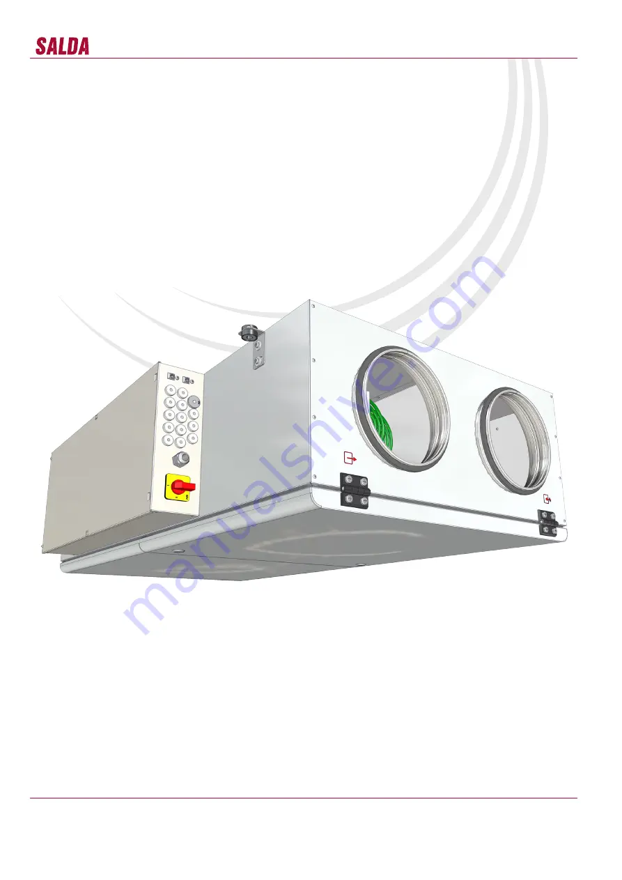
RIS 400_700PE-PW EKO 3.0_P0023_AP_0004
REKUPERATORINIAI ĮRENGINIAI
CENTRALE DI VENTILAZIONE CON RECUPERO DI CALORE
AHU WITH HEAT RECOVERY
LÜFTUNGSGERÄTE MIT WÄRMERÜCKGEWINNUNG
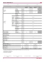
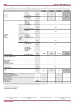
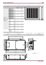
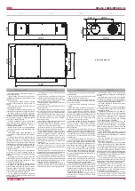
RIS 400PE/PW EKO 3.0
RIS 700PE/PW EKO 3.0
Techninis vadovas
[ lt ]
Manuale di uso e manutenzione
[ it ]
Technical manual
[ en ]
Bedienungsanleitung
[ de ]


