background image

2010 MODEL 699 40FT DISC CULTIVATOR

ASSEMBLY AND PARTS MANUAL

Summary of Contents for 699

Page 1: ...2010 MODEL 699 40FT DISC CULTIVATOR ASSEMBLY AND PARTS MANUAL...

Page 2: ...Assembly 22 8000 lb Tandem Axle Assembly 24 8000 lb Hub and Spindle Assembly 26 5000 lb Hub and Spindle Assembly 28 Shank Assembly Shank Assembly and Parts 30 Shank Head Parts 32 40 Shank Layout 33 D...

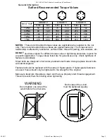
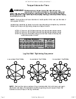
Page 3: ...XUH LV JLYHQ IRU D VSHFLILF DSSOLFDWLRQ 7RUTXH YDOXHV OLVWHG DUH IRU JHQHUDO XVH RQO KHFN WLJKWQHVV RI IDVWHQHUV SHULRGLFDOO 6KHDU EROWV DUH GHVLJQHG WR IDLO XQGHU SUHGHWHUPLQHG ORDGV OZD V UHSODFH VK...

Page 4: ...ally hazardous situation that if not avoided may result in MINOR or MODERATE INJURY Replace any DANGER WARNING CAUTION or instructional decal that is not readable or is missing The location and part n...

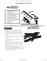
Page 5: ...ut hand and face protection A tiny almost invisible leak can penetrate skin thereby requiring immediate medical attention Use cardboard or wood to detect leaks never your hands Double check that all i...

Page 6: ...Torque to 20 25 ft lbs following the appropriate pattern below STEP 2 Torque to 55 60 ft lbs following the appropriate pattern below STEP 3 Torque to final ft lbs rating see bolt size below following...

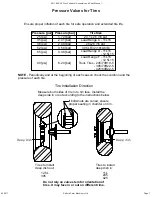
Page 7: ...k the condition and the pressure of each tire Tire Installation Direction Do not rely on valve stem for orientation of tires It may face in or out on different rims Measure both sides of tire in to ri...

Page 8: ...3 4 6 Wing lock pins at front only Place wing lock pins in holders when not in use Place wing lock pins through lugs when wings are raised to hold wings in raised position for transport or storage 1...

Page 9: ...S3536 3 1 2 BORE x 36 STROKE HYD CYLINDER 2 4 GPHF1600338H04 1 x 3 3 8 SHOULDER PIN HARDENED W FLATS 3 4 GP1600512A05 PIN 1 DIA x 5 1 2 LG 2 HOLES 4 8 BF16S 1 SAE WASHER 5 4 BSC0415 1 4 x 1 1 2 COTTER...

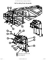
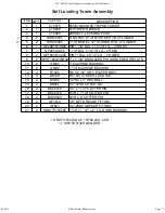
Page 10: ...Farm Machinery Ltd Page 10 2011 699 40 Disc Cultivator Assembly and Parts Manual 06 2011 12 13 17 8 2 1 10 6 15 14 20 11 18 7 21 4 19 3 16 9 5 34ft UP RT99 24ft 30ft 32ft UNDER Self Leveling Tower As...

Page 11: ...4 LG 2 HOLES 7 1 GP20010A05 1 1 4 DIA x 10 1 4 LG 2 HOLE 8 2 GP1600614A05 PIN 1 DIA x 6 1 4 LG 2 HOLES 9 2 GPHF1600338H04 1 x 3 3 8 SHOULDER PIN HARDENED W FLATS 10 4 GM26 1 MACHINE BUSHING 11 2 GM30...

Page 12: ...699 40 Disc Cultivator Assembly and Parts Manual 06 2011 335cm 498cm 335cm 107cm 102cm 123cm 151cm 61cm 151cm 123cm 102cm 107cm 33cm 33cm 47cm FRONT 3 4 3 Start here by lining up this extension with...

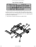
Page 13: ...D TUBE 4 x 6 x 1 4 W x 196 LG 5 56 BU1260 3 4 x 6 x 6 1 2 U BOLT 6 112 BN12L 3 4 NC NYLOCK NUT REAR 5TH BAR INSTALLATION 1 Mount 23 extensions 1 2 to rear of main frame at positions shown in layout Re...

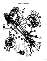
Page 14: ...ator Assembly and Parts Manual 06 2011 2 3 4 5 6 16 19 17 13 10 26 27 28 29 30 33 31 32 9 35 36 1 14 15 18 24 7 23 21 34 8 11 12 7 21 20 25 22 23 Insert metal plug in top port Pin to face rear of mach...

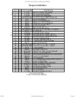
Page 15: ...5 000 LB SAFETY CHAIN 48 LG 15 1 L01063 35 000 LB SAFETY CHAIN ADAPTOR 16 1 PPI 42XL CAT 4 CAST IRON HITCH 17 2 B1680H 1 x 8 NC HEX BOLT GR 8 18 4 BF16HS 1 HARD STRUCTURAL WASHER 19 2 BN16L 1 8 NC NYL...

Page 16: ...IPTION 1 1 A60104 OPERATOR STATION HOSE HOLDER 2 1 G106 HD OPERATORS MANUAL HOLDER 3 1 GL11750 LIGHT PLUG HOLDER PLASTIC 4 4 P0160B HOSE CLAMP 4 5 5 BC0205 10 24 x 1 2 A307A LOW CARBON ZINC CARRIAGE B...

Page 17: ...15FI TIRE LOAD RANGE D RH WING AXLE INSTALLATION HSR3708 CYLINDER 5000 LB HUBS 11 x 15FI TIRE LOAD RANGE D MAIN AXLE INSTALLATION HSR4008 CYLINDER 8000 LB HUBS 12 5L x 15FI TIRE LOAD RANGE F MAIN AXLE...

Page 18: ...21 13 21 LH SHOWN RH SIMILAR Put pin 9 in tube for storage working position Put pin 9 in hole for transport position 22 RH 1 Use this hole on rear Use this hole on front LH 27 28 29 26 Note on 30ft 6...

Page 19: ...8 x 4 1 2 hex bolts 23 and 5 8 locknuts 24 6 Apply grease to all fittings Notice Salford uses replaceable bushings item 27 30 These are slightly oversized and need to be tapped into place with a hamm...

Page 20: ...Ltd Page 20 2011 699 40 Disc Cultivator Assembly and Parts Manual 06 2011 66 168cm INITIAL SETTING 4 11 12 8 7 11 LH SHOWN RH SIMILAR 1 6 13 14 17 18 16 5 10 2 LH RH 3 22 19 20 21 21 9 11 15 10 699 W...

Page 21: ...6 over turnbuckle and attach to frame with 1 x 3 1 4 head pin 10 and 1 4 x 1 1 2 cotter pin 11 Secure turnbuckle lock to turnbuckle with 1 2 x 3 1 2 L pin 17 and 11 hairpin 18 3 Attach 3 3 4 x 8 hydra...

Page 22: ...ultivator Assembly and Parts Manual 06 2011 12 5L x 15 HIGHWAY SERVICE TIRES 21 20 8 6 7 13 12 10 11 15 9 14 5 USE INNER HOLE FOR REAR USE OUTER HOLE FOR FRONT 19 18 1 LH 3 RH 2 LH 4 RH 16 17 22 23 21...

Page 23: ...UNTERFACE 9 1 GW14112 14 000 LB DUST CAP 10 1 BN28SF 1 3 4 NF SLOTTED FLANGE NUT 11 1 BSR0527 5 16 x 2 3 4 ROLL PIN 12 1 GB28995 12000 LB CONE 10000 LB INNER CONE 13 1 GB28921 12000 LB CUP 10000 LB IN...

Page 24: ...y and Parts Manual 06 2011 1 2 5 6 23 24 23 22 22 21 20 19 18 17 16 15 14 11 25 26 3 LH LH LH RH RH RH For wings For main frames 27 28 12 13 C SHANK S TINE 7 8 9 10 4 17 16 15 14 30 13 12 11 S TINE MA...

Page 25: ...BEAM WING RH 11 1 GW8110VW 8000 LB V SEAL GRASS WRAP GUARD 12 1 GW8110VS 8000 LB V SEAL 13 1 GW8110VC 8000 LB V SEAL COUNTERFACE 14 1 GB506849 8000 INNER CONE 15 1 GB506810 8000 INNER CUP 16 1 GB5013...

Page 26: ...ord Farm Machinery Ltd Page 26 2011 699 40 Disc Cultivator Assembly and Parts Manual 06 2011 1 2 5 6 7 8 9 10 12 11 13 14 3 4 4 6 7 8 12 5 15 2 3 2 3 4 16 2 3 4 6 5 7 8 17 8000 lb Hub and Spindle Asse...

Page 27: ...VS 8000 LB V SEAL 4 1 GW8110VC 8000 LB V SEAL COUNTERFACE 5 1 GB506849 8000 INNER CONE 6 1 GB506810 8000 INNER CUP 7 1 GB501310 8000 OUTER CUP 8 1 GB501349 8000 OUTER CONE 9 1 GW8108 1 SPINDLE WASHER...

Page 28: ...ford Farm Machinery Ltd Page 28 2011 699 40 Disc Cultivator Assembly and Parts Manual 06 2011 1 2 3 4 5 6 13 7 8 9 12 10 11 2 3 4 14 2 3 4 5 6 7 8 12 16 2 3 4 6 5 7 8 15 5000 lb Hub and Spindle Assemb...

Page 29: ...5000 LB SEAL COUNTERFACE 5 1 GB603049 5000 5500 LB INNER CONE 6 1 GB603011 5000 5500 LB INNER CUP 7 1 GB48510 5000 5500 LB OUTER CUP 3000 LB INNER CUP 8 1 GB48548 5000 5500 LB OUTER CONE 3000 LB INNER...

Page 30: ...rm Machinery Ltd Page 30 2011 699 40 Disc Cultivator Assembly and Parts Manual 06 2011 1 4 9 6 7 8 5 14 13 3 10 11 12 2 1 FOR 4 x 6 BEAM 2 FOR 3 x 6 BEAM 3 FOR 2 1 2 BEAM Shank Assembly and Parts Shan...

Page 31: ...w bolts 13 and 7 16 heavy hex nuts 14 3 Mount shanks on frame using 5 8 u bolt 1 2 or 3 and 5 8 lock nuts 4 See shank layout drawing for shank mounting locations ITEM QTY PART NO DESCRIPTION 1 2 BU106...

Page 32: ...1 C90124 OUTER C SHANK WELDMENT 2 1 C90122 INNER C SHANK WELDMENT 3 2 A60059 1 OD 3 4 ID X 1 15 16 LONG BUSHING 4 1 B1265 3 4 NC x 6 1 2 LG HEX BOLT GR 5 5 1 BN12J 3 4 JAM NUT 6 1 BN10J 5 8 NC JAM NUT...

Page 33: ...tor Assembly and Parts Manual 45 9 70 70 24 24 17 50 39 27 42 17 17 15 66 19 66 15 17 42 17 45 4 9 17 50 27 39 22 19 42 11 34 47 44 44 39 39 19 42 22 4 14 14 62 42 42 62 11 47 34 22 22 67 699 40 SHANK...

Page 34: ...ultivator Assembly and Parts Manual 06 2011 44 114 68 123 28 89 123 122 88 122 67 44 1 2 4 4 4 4 3 3 3 3 3 3 3 3 699 40 DISC CULTIVATOR GANG MOUNT LOCATIONS See gang installation drawing for part numb...

Page 35: ...1 c m s h a ft 2 1 8 c m s c ra p e r tu b e 1 1 b la d e s 2 4 1 c m s h a ft 2 1 8 c m s c ra p e r tu b e 8 b la d e s 1 7 4 c m s h a ft 1 7 3 c m s c ra p e r tu b e 3 2 5 c m g a n g tu b e 3 2...

Page 36: ...22 19 18 26 8 9 1 2 17 26 3 5 10 11 12 13 15 16 14 26 17 21 20 3 23 22 LH WING LH MAIN FRAME RH MAIN FRAME RH WING WING MAIN FRAME LH WING RH WING On c shank wings only not on s tine 4 Disc Gang Depth...

Page 37: ...nuts 22 See gang mount layout drawing for locations Do not tighten bolts yet leave them loose enough for adjustment 3 Set wing gang turnbuckles 8 to 45 117cm long pin to pin Attach to bolt on anchors...

Page 38: ...on gang mounts using 1 1 4 x 7 bolts 24 and 1 1 4 lock nuts 25 8 Mount cylinder lugs 5 to sub frames with 5 8 x 4 x 4 1 2 u bolts 23 and 5 8 lock nuts 22 Do not tighten bolts yet leave them loose enou...

Page 39: ...8 x 6 x 5 1 2 7 BU1020 5 8 x 2 x 3 1 2 U BOLT 8 BN10L 5 8 NYLOCK NUT NC 1 Assemble the gang hangers as shown on the following pages and mount gangs to gang tubes See gang layout drawing for gang tube...

Page 40: ...9 40 Disc Cultivator Assembly and Parts Manual 06 2011 8 3 2 1 4 16 10 5 6 5 6 7 5 14 12 11 6 9 12 15 Assemble with grease fittings pointing forward Only needed with 1 3 4 ID bearings 13 Replacement b...

Page 41: ...BOLT PLATED 5 6 BF12HS 3 4 HARD STRUCTURAL WASHER 6 5 BN12S 3 4 STOVER LOCK NUT 7 1 D10034 2 1 4 C FLEX PULL UP PLATE WITH STOPPER 8 1 B1275 3 4 NC x 7 1 2 LG HEX BOLT GR 5 9 1 D00071 1 1 2 TRUNNION B...

Page 42: ...E for 11 blade gang Torque nut to 1200 ft lbs 1630 Nm To torque gang nut 10 place a 6 ft 1 8m pipe over the wrench and apply 200 lbs 90 kg to the end of the extension When the nut stops tightening fr...

Page 43: ...EARING ASSEMBLY 18 ZD251008 2 1 2 OD X 1 1 2 LG SPACER 22 56cm 1 20 51cm 2 A B C A for 7 blade gang B for 8 blade gang C for 9 blade gang D for 10 blade gang E for 11 blade gang 20 51cm blade at far e...

Page 44: ...Parts Manual 06 2011 1 4 2 3 4 3 ITEM NO QTY PART NO DESCRIPTION 1 1 C10971 699 GANG DEPTH POINTER BRACKET 2 1 C10972 699 GANG DEPTH POINTER 3 6 BN10S 5 8 NC STOVER LOCK NUT 4 4 BU1043 U BOLT 5 8 x 4...

Page 45: ...2 51 109 64 109 18 18 699 40 HARROW LAYOUT Dimensions in cm Handle Handle Handle Handle Handle Handle Harrow tool 4 TINES R634 4 TINES R634 3 TINES R633 3 TINES R633 6 TINES R636 5 TINES R635 6 2 ROLL...

Page 46: ...ford Farm Machinery Ltd Page 46 2011 699 40 Disc Cultivator Assembly and Parts Manual 06 2011 2 3 7 8 3 1 5 4 3 6 TOP 9 See harrow layout for harrow tool holder location 10 1 9 16 3 4 Harrow Installat...

Page 47: ...tool sits in holder Leave 3 4 between rollers on wings and rollers on main frame and leave 1 2 between all other rollers Hole settings for harrow heads to extensions ITEM NO PART NUMBER DESCRIPTION 1...

Page 48: ...48 2011 699 40 Disc Cultivator Assembly and Parts Manual 06 2011 8 14 6 9 17 21 22 12 23 2 1 10 11 20 24 9 7 7 25 FLIP SPACER OVER FOR S TINES 5 4 16 3 6 19 18 13 27 9 8 26 STANDARD POSITION AS SHOWN...

Page 49: ...NC 9 6 BN10L 5 8 NYLOCK NUT NC 10 1 GP0800312L03 1 2 x 3 1 2 PARKING STAND PIN 11 1 GHP11 11 HAIR PIN 12 2 R0035 2 x 10 HARROW ARM SPRING 13 1 R80128 ROLLER ARM STOP BRACKET LONG 14 1 R80037L TINE SE...

Page 50: ...1 1 19 14 MOUNTS ONLY FOR ENDS OF FOR ADJUSTOR 10 MACHINE SPECIFIC POSITIONS 4 16 ALL OTHER SEE HARROW LAYOUT FOR 5 POSITIONS FRONT TUBE ONLY 9 2 18 14 21 8 17 14 16 6 11 6 12 15 20 3 13 16 TINE ANGLE...

Page 51: ...ECTOR 4 R30011 CLAMP BRACKET 5 B0812 1 2 X 1 1 4 BOLT 6 BN08L 1 2 NYLOCK NUT NC 7 BU1025 U BOLT 5 8 x 2 1 2 x 4 8 BN10L 5 8 NYLOCK NUT NC 9 R60000 1 2 WIRE 20 DBL LEG SPRING TINE 10 R30007 ADJUSTING B...

Page 52: ...ts Manual 06 2011 7 3 4 5 2 6 1 5 ROLLER SHOWN Install bearing with grease fitting facing rear of roller Arrow shows roller rotation direction 40HR Install grease decal towards rear of frame SALFORD D...

Page 53: ...LY 4 0 121 9 LONG COMPLETE ASSEMBLY PART NO MR80144 L R 14 ROLLER HARROW ASSEMBLY 3 0 91 4 LONG COMPLETE ASSEMBLY PART NO MR80143 L R 14 ROLLER HARROW ASSEMBLY 6 2 187 9 LONG COMPLETE ASSEMBLY PART NO...

Page 54: ...tating this clip will increase or decrease downpressure of roller INCREASE To change the height of the arm rotate block block has three different settings Frame angle adjust raise front rank HARROW SE...

Page 55: ...standard setting as shown above Here the rake angle is varied Here the tine section is angled by changing the bolt hole used Shown here is the standard setting For better trash flow the tines are adj...

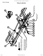
Page 56: ...ts Manual 06 2011 1 6 1B 3 4 5 3 5 4 1 1B 2 E H L F G D B C C B Route hoses along frame Clamp to frame at bolts Run hoses through rings on tongue Leave a small droop of hose at hinge points A A 5 5 6...

Page 57: ...O THE TRACTOR ON HARD GROUND DRAWBAR MAY BE BENT UPWARDS Use tie straps to identify the hose ends with coloured straps for quick hookup to tractor LABEL LENGTH cm QTY FROM TO 1A 716 1 TRACTOR STROKE C...

Page 58: ...to Front Right Base RRB to Rear Right Base FLR to Front Left Rod RLR to Rear Left Rod FLB to Front Left Base RLB to Rear Left Base ROD to Tractor Green Grey BASE to Tractor Green 7B 8R 9 9 10 10 11 1...

Page 59: ...ing cylinders will cause wings to fall to the ground Whenever air could have entered the cylinders repeat the process above to purge circuit Never work on a lift system with the wings folded ALWAYS UN...

Page 60: ...r Assembly and Parts Manual 06 2011 17 13 14 15 16 A B C D G Run Hoses along frame members and through rings Clamp down to frame at bolts Ball valve at rod side of cylinder When in transport or storag...

Page 61: ...extend discs hold for 10 seconds When machine is not in use close ball valve LABEL LENGTH cm FROM TO 13 1082 TRACTOR BASE OF 4008 A 14 513 ROD OF 4008 A BASE OF 3708 B 15 366 ROD OF 3708 B BASE OF 350...

Page 62: ...Salford Farm Machinery Ltd Page 62 2011 699 40 Disc Cultivator Assembly and Parts Manual 06 2011 8 7 12 9 13 9 RED FACING REAR 1 2 11 10 12 10 13 3 7 8 4 6 5 Lights SMV Install...

Page 63: ...L00425 OUTSIDE LIGHT MOUNTING PLATE 3 1 C1011 SMV MOUNTING BRACKET 4 1 GAP103NS SMV SIGN 5 2 BN06L 3 8 16NC LOCK NUT 6 2 B0610 3 8 X 1 PLATED BOLT GR 5 7 3 BU1061 U BOLT 5 8 x 6 x 5 1 2 8 6 BN10L 5 8...

Page 64: ...Salford Farm Machinery Ltd 364018 McBeth Road N0J 1W0 Salford Ontario Canada www salfordmachine com 1 866 442 1293...

Reviews: