


Mega-Bore Short-body
Open-Center Hydraulic Cylinder
Instruction Manual
SD
SDL
대 관 통 경 박 형
중 공 유 압 실 린 더
취 급 설 명 서
标 准 开 心 式 油 缸
说
明
书
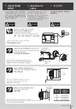
실린더를 조작하기 전에 이 설명서의
위험/경고 항목을 잘 읽고 숙지해
주십시오.
이 설명서를 궁금한 사항이나 점검할 사
항 등 필요할 때 참조할 수 있도록 잘
보관하십시오.
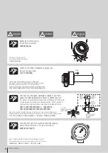
IMPORTANT
重要
중요
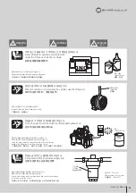
请仔细阅读并了解危险/警告 本评估
手册项目営业前 气缸。
请妥善保存本手册的答案在你身边的
任何问题,你可能并检查。
Please read and understand DANGER/
WARNING items in this maunal before
operating the cylinder.
Please keep this manual by your side
for answers to any questions you may
have and to check.
Summary of Contents for SD
Page 2: ......
Page 31: ...31 Instruction Manual n o t e...
Page 35: ...35 Instruction Manual n o t e...
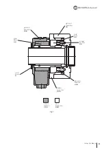
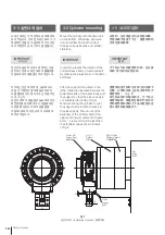
Page 38: ...21 26 19 20 23 25 18 17 22 16 15 24 38 Rotary Cylinder Fig 14...
Page 45: ......
Page 46: ......
Page 47: ......


