background image

Mounting and 

Operating Instructions

EB 8111/8112 EN


Tr

anslat

ion of original instruct

ions

Edition July 2016

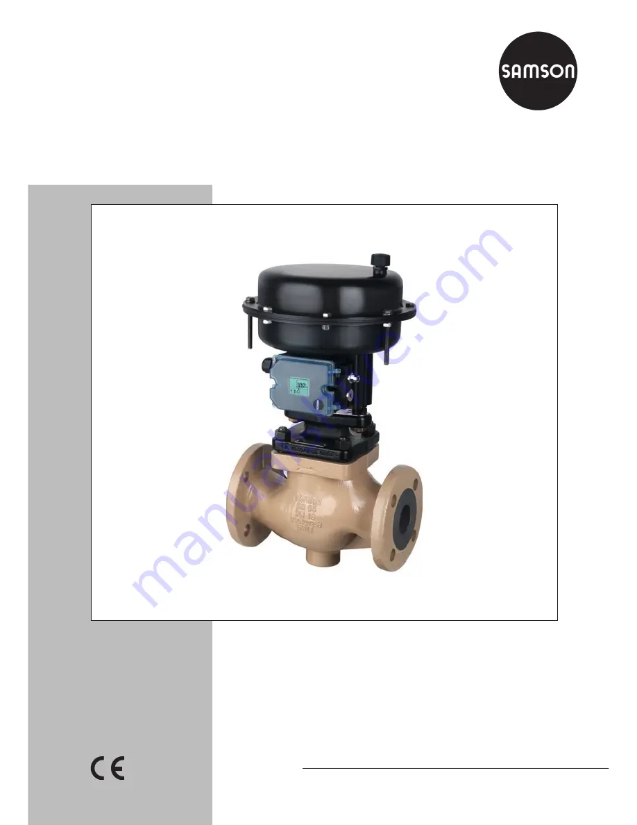
Type 3321 Valve

In combination with actuators, 

e.g. SAMSON Type 3372 Electropneumatic Actuator, 

Type 3371 Pneumatic Actuator, Type 5824/5825 Electric 

Actuator, or Type 3374 Electric Actuator

DIN and ANSI versions

Summary of Contents for 3321

Page 1: ...lation of original instructions Edition July 2016 Type 3321 Valve In combination with actuators e g SAMSON Type 3372 Electropneumatic Actuator Type 3371 Pneumatic Actuator Type 5824 5825 Electric Actu...

Page 2: ...Department aftersalesservice samson de The mounting and operating instructions for the devices are included in the scope of delivery The latest documentation is available on our website www samson de...

Page 3: ...16 3 3 Technical data 18 4 Measures 22 4 1 Unpacking 22 4 2 Transporting and lifting 22 4 2 1 Transporting 23 4 2 2 Lifting 23 4 3 Storage 25 4 4 Preparation for installation 26 5 Mounting and start u...

Page 4: ...B 42 7 3 2 For mounting on rods Form C 43 7 4 Preparation for return shipment 44 7 5 Ordering spare parts and operating supplies 44 8 Malfunctions 46 8 1 Troubleshooting 46 8 2 Emergency action 47 9 D...

Page 5: ...urpose or for damage caused by external forces or any other external factors Refer to the technical data and nameplate for limits and fields of application as well as possible uses Reasonably foreseea...

Page 6: ...jury or property damage plant operators and operating personnel must prevent hazards that could be caused in the control valve by the process medium the operat ing pressure the signal pressure or by m...

Page 7: ...l bonding system observe the requirements specified in section 6 4 of EN 60079 14 VDE 0165 Part 1 Referenced documentation The following documents apply in addition to these mounting and operating ins...

Page 8: ...on While working on the control valve disconnect and lock the pneumatic air supply as well as the control signal Risk of personal injury when the pneumatic actuator vents While the valve is operating...

Page 9: ...up Wear protective clothing and gloves 1 3 Notes on possible property damage NOTICE Risk of damage to the electric control valve due to the power supply exceeding the permissible tolerances The elect...

Page 10: ...r Parts that are too loose may cause leak age Observe the specified tightening torques u AB 0100 Risk of valve damage due to the use of unsuitable tools Certain tools are required to work on the valve...

Page 11: ...EB 8111 8112 EN 11 Safety instructions and measures...

Page 12: ...of manufacture 10 Valve size DIN DN ANSI NPS JIS DN A B 11 Pressure rating DIN PN ANSI CL JIS K 12 Order no with modification index For after sales service orders AA prefix 13 Position in order For a...

Page 13: ...80 Fig 2 Nameplate on the body Fig 3 Nameplate on the bonnet 2 2 Actuator nameplate See associated actuator documentation 2 3 Material number The seat and plug of the valves have an arti cle number w...

Page 14: ...sembled in the body 1 The plug stem is connected to the actuator stem A3 A7 by a stem connector A30 A31 and sealed by the spring loaded packing 15 The process medium flows through the valve in the dir...

Page 15: ...lug stem 8 Threaded bushing packing nut 13 Stud bolt 14 Body nut 15 Packing 17 Body gasket 96 Flange bonnet 97 Flange 98 Central nut A3 A7 Actuator stem A11 A33 Rod A17 Bracket A25 Nut A30 A31 Stem co...

Page 16: ...open The direction of action of the electric and electropneumatic actuators is determined by the actuator version The direction of action of the Type 3371 Pneumatic Actuator can be reversed if re qui...

Page 17: ...ing using crossbeam and central nut Form B attachment Type 3321 PP Type 3321 IP Type 3321 E1 Type 3321 E3 A17 98 Fig 7 Mounting using rods Form C attach ment Type 3321 PP Type 3321 IP A33 A60 Legend f...

Page 18: ...for a temperature range from 10 to 220 C 14 to 430 F The use of an insulating section extends the temperature range to 300 C 572 F Leakage class Depending on the version the following leakage class ap...

Page 19: ...in Table 2 The dimensions and weights for the ANSI versions are listed in Table 3 Refer to the following data sheets for more dimensions and weights u T 8313 for Type 3372 Electropneumatic Actuator u...

Page 20: ...Valve ANSI version Valve size NPS 1 1 2 2 3 4 DN 15 20 25 40 50 65 80 100 L Class 150 in 7 25 7 25 7 25 8 75 10 00 10 87 11 75 13 87 mm 184 184 184 222 254 276 298 352 L Class 300 in 7 50 7 62 7 75 9...

Page 21: ...EB 8111 8112 EN 21 Design and principle of operation Dimensional drawings DN 15 to 50 NPS to 2 H1 a L H2 DN 65 to 100 NPS 2 to 4 H1 a L H2 Version with insulating section H4 H4...

Page 22: ...otective caps fitted on the valve s inlet and outlet prevent foreign particles from en tering the valve and damaging it Do not remove the protective caps until im mediately before installing the valve...

Page 23: ...xternal influences e g impact Do not damage the corrosion protection paint surface coatings Remove any damage immediately Protect the control valve against moisture and dirt The permissible transporta...

Page 24: ...er the lifting equipment and acces sories can bear the weight 3 Move the control valve at an even pace to the site of installation 4 Install the valve into the pipeline see sec tion 5 2 3 5 After inst...

Page 25: ...than 75 In damp spaces prevent condensation If necessary use a drying agent or heating Make sure that the ambient air is free of acids or other corrosive media The permissible storage temperature of s...

Page 26: ...nation valve size material pressure rat ing and temperature range of the valve match the plant conditions size and pressure rating of the pipeline medium temperature etc For steam applications make su...

Page 27: ...EB 8111 8112 EN 27 Measures...

Page 28: ...valve and actuator have not been assembled by SAMSON Remove the mounted actuator before mounting the other actuator see associat ed actuator documentation Preloading the actuator springs increases th...

Page 29: ...2 4 0 3 Ma 0 7 2 10 Vapor Ma 0 3 1 2 4 0 3 Ma 0 7 1 2 10 Saturated steam percentage of condensate 5 2 20 Liquid Free of cavitation w 10 m s 2 4 Cavitation producing noise w 3 m s 2 4 Cavitation produc...

Page 30: ...ir intake to pre vent a vacuum from forming in the device Locate the vent plug on the opposite side to the workplace of operating personnel On mounting valve accessories make sure that they can be ope...

Page 31: ...f valve damage due to a sudden pres sure increase and resulting high flow veloci ties Slowly open the shut off valve in the pipeline during start up 8 Check the valve to ensure it functions properly 5...

Page 32: ...ditions are met Retract the plug stem to open the valve Observe the maximum permissible pres sure for valve and plant The plant engineering company is responsible for performing the pressure test SAMS...

Page 33: ...EB 8111 8112 EN 33 Mounting and start up...

Page 34: ...Type 3371 Pneumatic Actuator vents Wear eye protection when working in close proximity to the control valve Risk of burn injuries due to hot or cold com ponents and pipelines Depending on the process...

Page 35: ...EB 8111 8112 EN 35 Operation...

Page 36: ...depressurize all plant sections con cerned and the valve Drain the process medium from all the plant sections concerned as well as the valve Wear personal protective equipment Risk of personal injury...

Page 37: ...nts Only use lubricants approved by SAMSON u AB 0100 The control valve was checked by SAMSON before it left the factory Certain test results seat leakage and leak test certified by SAMSON lose their v...

Page 38: ...bonnet 96 and the flange 97 over the studs 13 onto the body 6 Press the plug 5 firmly into the seat 4 while fastening down the flange bonnet 96 with the body nuts 14 Tighten the nuts gradually in a cr...

Page 39: ...lve bonnet 2 and plug with plug stem 5 onto the body 6 Press the plug 5 firmly into the seat 4 while fastening down the valve bonnet 2 with the body nuts 14 Tighten the nuts gradually in a criss cross...

Page 40: ...g a suitable tool 7 Renew damaged parts Clean the pack ing chamber thoroughly 8 Apply a suitable lubricant to all the pack ing parts and to the plug stem 5 9 Slide the plug with plug stem 5 into the v...

Page 41: ...Renew the damaged parts and carefully clean the packing chamber 8 Apply a suitable lubricant to all the pack ing parts and to the plug stem 5 9 Slide the plug with plug stem 5 into the valve body 1 1...

Page 42: ...uitable tool 8 Apply a suitable lubricant to the thread and the sealing cone of the new seat 9 Screw in the seat 4 Observe tightening torques 10 Apply a suitable lubricant to all the pack ing parts an...

Page 43: ...0 Screw in the seat 4 Observe tightening torques 11 Apply a suitable lubricant to all the pack ing parts and to the new plug stem 5 We recommend replacing the packing as well See section 7 2 2 12 Slid...

Page 44: ...s for after sales service Declaration on Contamination 4 Send the valve together with the filled in form to your nearest SAMSON subsidi ary SAMSON subsidiaries are listed on our website at u www samso...

Page 45: ...EB 8111 8112 EN 45 Servicing...

Page 46: ...Actuator or plug stem does not move through the whole range Signal pressure too low Check the signal pressure Check the signal pressure line for leakage No or incorrect power supply connected Check th...

Page 47: ...1 Close the shut off valves upstream and downstream of the control valve to stop the process medium from flowing through the valve 2 Check the valve for damage If neces sary contact SAMSON s After sa...

Page 48: ...valve While working on the valve residual process medium can escape and depending on its properties may lead to personal injury e g chemical burns Wear protective clothing gloves and eye wear Risk of...

Page 49: ...eline see section 4 2 9 3 Removing the actuator from the valve See associated actuator documentation 9 4 Disposal Observe local national and internation al refuse regulations Do not dispose of compone...

Page 50: ...ries representatives and service facilities worldwide can be found on the SAMSON website in all SAMSON product catalogs or on the back of these Mounting and Operat ing Instructions Required specificat...

Page 51: ...uids G2 L1 L2 1 1 Gase nach Art 4 Abs 1 Pkt c i zweiter Gedankenstrich Gases acc to Article 4 Section 1 Subsection c i second indent Fl ssigkeiten nach Art 4 Abs 1 Pkt c ii Liquids acc to Article 4 Se...

Page 52: ...Fluide all Fluids Einzeldrosselscheibe mehrstufig mit Anschwei ende Single attenuation plate multi stage with welding end Durchgangsventil Globe Valve 240 3241 ANSI Geh use GG Cl125 ab 5 Cast iron Bo...

Page 53: ...EB 8111 8112 EN 53...

Page 54: ...net including guide bushing 4 Seat 5 Plug with plug stem 8 Threaded bushing packing nut 11 Spring 12 Washer 13 Stud bolt 14 Body nut 15 Packing 16 V ring packing 17 Body gasket 19 Spacer 62 Flow divid...

Page 55: ...EB 8111 8112 EN 55 15 11 12 16 2 5 1 4 13 17 14 63 62 5 2 8 Type 3321 DN 65 to 100 NPS 2 to 4...

Page 56: ...SAMSON AG MESS UND REGELTECHNIK Weism llerstra e 3 60314 Frankfurt am Main Germany Phone 49 69 4009 0 Fax 49 69 4009 1507 samson samson de www samson de EB 8111 8112 EN 2016 12 08 English...

Reviews: