background image

Mounting and 

Operating Instructions

EB 8091-1 EN


Tr

anslat

ion of original instruct

ions

Edition September 2016

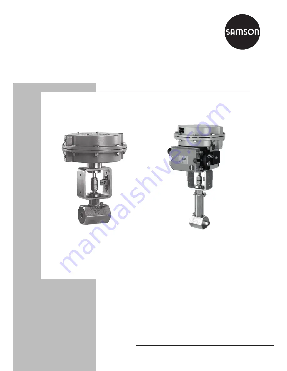
Type 3510-1 (left) and Type 3510-7 (right) Pneumatic Control Valves

Type 3510 Micro-flow Valve

In combination with an actuator,


e.g. a SAMSON Type 3271 or Type 3277 Pneumatic Actuator

ANSI version

Summary of Contents for 3510

Page 1: ...ranslation of original instructions Edition September 2016 Type 3510 1 left and Type 3510 7 right Pneumatic Control Valves Type 3510 Micro flow Valve In combination with an actuator e g a SAMSON Type...

Page 2: ...epartment aftersalesservice samson de The mounting and operating instructions for the devices are included in the scope of delivery The latest documentation is available on our website www samson de P...

Page 3: ...nical data 14 4 Measures for preparation 20 4 1 Unpacking 20 4 2 Transporting and lifting 20 4 2 1 Transporting 20 4 2 2 Lifting 20 4 3 Storage 21 4 4 Preparation for installation 21 5 Mounting and st...

Page 4: ...39 7 4 Preparation for return shipment 40 7 5 Ordering spare parts and operating supplies 41 8 Malfunctions 42 8 1 Troubleshooting 42 8 2 Emergency action 43 9 Decommissioning and disassembly 44 9 1...

Page 5: ...for its intended purpose or for damage caused by external forces or any other external factors Refer to the technical data and nameplate for limits and fields of application as well as possible uses R...

Page 6: ...or property damage plant operators and operating personnel must prevent hazards that could be caused in the control valve by the process medium the operat ing pressure the signal pressure or by moving...

Page 7: ...on The following documents apply in addition to these mounting and operating instructions Mounting and operating instructions for mounted actuator e g u EB 8310 1 for Type 3271 and Type 3277 Pneumatic...

Page 8: ...ection when working in close proximity to the control valve Risk of personal injury due to preloaded springs Valves in combination with pneumatic actuators with preloaded springs are under ten sion Th...

Page 9: ...d accordingly see sec tion 2 3 Only install matching trim parts Risk of valve damage due to contamination e g solid particles in the pipeline The plant operator is responsible for cleaning the pipelin...

Page 10: ...ode and damage the valve surface Only use lubricants approved by SAMSON u AB 0100 2 Markings on the control valve 2 1 Body inscription SAMSON 3510 1 2 4 6 5 3 8 7 Fig 1 Body inscription 1 Valve size D...

Page 11: ...e on the trim See Fig 2 Plug material Seat material KVS CV Characteristic SAMSON consecutive number Anti rotation fixture on the bellows seal Bellows material Nominal pressure Incorrect control due to...

Page 12: ...e is deter mined by the diaphragm area The medium flows through the valve in the direction indicated by the arrow A rise in signal pressure causes the force acting on the diaphragm in the actuator to...

Page 13: ...Slotted round nut 12 Threaded bushing packing nut 13 Yoke 14 Travel indicator scale 20 Hexagon nut 34 Packing A7 Actuator stem A8 Ring nut A27 1 Stem connector nut A27 2 Bearing sleeve bottom part of...

Page 14: ...tuator must be preloaded so that the travel ranges match See associ ated actuator documentation The basic pneumatic actuator can be re placed by a pneumatic actuator with addi tional handwheel or by a...

Page 15: ...ut noise emission as it depends on the valve version plant facilities and process medium On request SAMSON can perform calculations according to IEC 60534 Part 8 3 and Part 8 4 or VDMA 24422 edi tion...

Page 16: ...lass 150 in 2 91 74 mm 7 25 7 25 7 25 7 25 7 25 mm 184 184 184 184 184 Class 300 in 7 50 7 75 7 50 7 62 7 75 mm 190 197 190 194 197 Class 600 in 8 00 8 25 8 00 8 12 8 25 mm 203 210 203 206 210 Class 9...

Page 17: ...5 263 mm Bellows seal up to Class 1500 14 37 365 mm H2 or flange D1 Class 150 in 0 90 2 23 mm 2 0 90 2 23 mm 2 0 90 2 23 mm 2 3 54 3 94 4 33 mm 90 100 110 Class 300 in 3 74 4 53 4 91 mm 95 115 125 Cla...

Page 18: ...Design and principle of operation Dimensional drawings L L1 SW50 57 SW46 L1 H4 H2 H1 Type 3510 as angle valve with female thread Type 3510 as globe valve with female thread with bellows seal or insul...

Page 19: ...8 to NPS NPS 1 NPS NPS NPS 1 Valve without actuator Class 150 lbs 3 74 4 0 5 8 7 3 8 2 kg 1 7 1 8 2 6 3 3 3 7 Class 300 lbs 3 74 4 0 7 1 9 3 10 6 kg 1 7 1 8 3 2 4 2 4 8 Class 600 lbs 3 74 4 0 7 5 10 6...

Page 20: ...detailed transport and lift ing instructions on request 4 2 1 Transporting The control valve can be transported using lifting equipment e g crane or forklift Leave the control valve in its transport...

Page 21: ...bient air is free of acids or other corrosive media The permissible storage temperature of standard control valves is 4 to 149 F 20 to 65 C Contact SAMSON s After sales Service de partment for the sto...

Page 22: ...s size and pressure rating of the pipeline medium temperature etc For steam applications make sure that the pipelines are dry Moisture will dam age the inside of the valve Check any mounted pressure g...

Page 23: ...alve and actuator have not been assembled by SAMSON Remove the mounted actuator before mounting the other actuator see associat ed actuator documentation Preloading the actuator springs increases the...

Page 24: ...opposite side to the workplace of operating personnel On mounting valve accessories make sure that they can be operated from the workplace of the operating personnel Table 3 Inlet and outlet lengths...

Page 25: ...ection G 1 8 at the top flange allow the sealing ability of the bellows to be moni tored Particularly for liquids and vapors as well as explosive or hazardous substances we rec ommend installing a sui...

Page 26: ...t the actuator stem to protect the plug from sparks during weld ing 3 Weld the valve free of stress into the pipeline 4 Proceed as described for Version with fe male thread or flanges steps 6 to 8 5 3...

Page 27: ...akage to the atmo sphere visual inspection 4 Repeat steps 1 and 2 until the packing completely seals the valve If the adjustable packing does not seal prop erly contact SAMSON s After sales Service de...

Page 28: ...injuries due to hot or cold com ponents and pipelines Depending on the process medium valve components and pipelines may get very hot or cold and cause burn injuries Wear protective clothing and safe...

Page 29: ...EB 8091 1 EN 29...

Page 30: ...valve residual process medium can escape and depending on its properties may lead to personal injury e g chemical burns If possible drain any process medium resi dues from the plant sections concerne...

Page 31: ...the yoke 13 from the interme diate piece 4 3 Unscrew the fillister head screw 6 on the anti rotation fixture 2 4 Remove the anti rotation fixture 2 4 from the inter mediate piece 4 4 Unscrew the inte...

Page 32: ...d nut 12 Threaded bushing packing nut 13 Yoke 14 Travel indicator scale 20 Hexagon nut 34 Packing A7 Actuator stem A8 Ring nut A27 1 Stem connector nut A27 2 Bearing sleeve bottom part of the stem con...

Page 33: ...Remove the bottom section of the top an ti rotation fixture 24 2 from the insulat ing section 7 8 Remove the seal 5 Carefully clean the sealing faces in the intermediate piece 4 and insulating section...

Page 34: ...pply a suitable lubricant to the thread of the intermediate piece 4 20 Carefully place the intermediate piece 4 over the plug stem extension 22 onto the insulating section 7 Use a suitable tool to scr...

Page 35: ...nd bellows seal 7 9 Loosen the fillister head screw 6 on the bottom anti rotation fixture 3 5 10 Version without test connection remove the anti rotation fixture 3 5 from the bellows seal 7 11 Unscrew...

Page 36: ...bent end facing downward onto the bellows seal 7 19 Insert the new seal 3 4 into the bellows seal 4 20 Place the washer 27 on the bellows seal 7 21 Apply a suitable lubricant to the thread of the int...

Page 37: ...acking parts over the plug stem into the packing chamber us ing a suitable tool Observe the proper sequence see Fig 7 9 Screw in the threaded bushing 12 and tighten it Observe tightening torques 10 Ve...

Page 38: ...dard version 1 Remove the actuator from the valve See associated actuator documentation 2 Loosen the slotted nut 11 at the valve Remove the yoke 13 from the interme diate piece 4 3 Unscrew the fillist...

Page 39: ...ntermediate piece 4 out of the insulating section 7 and carefully lift it off the plug stem extension 22 6 Remove the washer 27 from the insulat ing section 7 7 Remove the bottom section of the top an...

Page 40: ...rmediate piece is fastened tight It must not be clamped down 26 Push the top section of the top anti rota tion fixture 24 2 with plug seat etc inscribed on it with the bent end facing upward over the...

Page 41: ...ary or the SAMSON After sales Service depart ment for information on spare parts lubri cants and tools Spare parts See section 10 2 for details on spare parts Lubricant Details on suitable lubricants...

Page 42: ...gnal pressure Check the signal pressure line for leakage The valve leaks to the atmo sphere fugitive emissions The packing is defective Replace packing see sec tion 7 2 or contact SAMSON s After sales...

Page 43: ...on 1 Close the shut off valves upstream and downstream of the control valve to stop the process medium from flowing through the valve 2 Check the valve for damage If neces sary contact SAMSON s After...

Page 44: ...roughly flush the pipelines The plant operator is responsible for cleaning the pipelines Wear protective clothing safety gloves and eyewear Risk of burn injuries due to hot or cold com ponents and pip...

Page 45: ...partment for support concerning service or repair work or when malfunctions or defects arise E mail You can reach the After sales Service De partment at aftersalesservice samson de Addresses of SAMSO...

Page 46: ...d bushing packing nut 13 Yoke 14 Travel indicator scale 15 Retaining plate 16 Countersunk screw 17 Bearing sleeve 18 Disk spring 19 Packing washer 20 Hexagon nut 21 Snap ring 22 Plug stem extension 23...

Page 47: ...Ch Nr WNR PN400 SAMSON 3510 PN 400 Ch WNR PN 400 Ch WNR PN 400 Ch WNR 14 15 16 13 20 21 19 18 17 8 9 9 10 8 2 4 2 2 2 3 2 1 4 6 24 2 27 24 2 27 3 4 3 3 3 1 3 2 3 5 29 30 6 7 3 11 26 5 24 1 7 6 22 25 1...

Page 48: ...SAMSON AG MESS UND REGELTECHNIK Weism llerstra e 3 60314 Frankfurt am Main Germany Phone 49 69 4009 0 Fax 49 69 4009 1507 samson samson de www samson de EB 8091 1 EN 2017 05 16 English...

Reviews: