background image

© 2007 Oasis Imaging Products, Inc.     

                                                                                                        Page 1 

Remanufacturing Instructions


Samsung ML3560


For Technical Support, please call (800) 322 8992 ext 110 


OEM Reference Information: 
 
Part #   


Yield @ 5%   

ML 3560D6 


6000 

ML 3560DB 


12000 


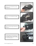
1. Remove the drum shutter arms from both 
ends of the cartridge to remove the drum 
shutter (Fig.1).  

Fig. 1 

 
2. Remove two screws from the contact side 
end cap (Fig. 2). Do not remove end cap at 
this time. 

Fig. 2 

Summary of Contents for ML-3560 Series

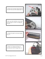
Page 1: ...rt please call 800 322 8992 ext 110 OEM Reference Information Part Yield 5 ML 3560D6 6000 ML 3560DB 12000 1 Remove the drum shutter arms from both ends of the cartridge to remove the drum shutter Fig 1 Fig 1 2 Remove two screws from the contact side end cap Fig 2 Do not remove end cap at this time Fig 2 ...

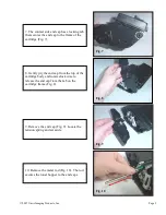
Page 2: ...4 Remove two screws from the gear plate Fig 4 5 Remove the gear and plate from the end cap Fig 5 6 Tension springs secure the end caps to the toner hopper on each side of the cartridge Use a spring hook tool to release the springs from each end cap Fig 6 Fig 3 Fig 4 Fig 5 Fig 6 Spring location ...

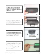
Page 3: ...artridge Fig 7 8 Gently pry the end cap from the top of the cartridge body and rotate clock wise to release the end cap from the tab on the cartridge frame Fig 8 9 Remove the end cap Fig 9 Locate the tension spring and set aside 10 Remove the metal rod Fig 10 The rod secures the toner hopper to the end caps Fig 7 Fig 8 Fig 9 Fig 10 ...

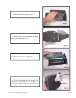
Page 4: ...per Fig 11 Fig 11 12 Remove the screw that secures the drum axle to the end cap Fig 12 13 Remove the drum unit Fig 13 14 On the toner hopper section make a note of the gear orientation Remove the large black gear and the white drive gear Fig 14 Fig 12 Fig 13 Fig 14 ...

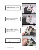
Page 5: ...move the remaining four gears 16 Remove the white bearing from the developer roller shaft Fig 16 17 On the opposite side of the hopper release the locking tab that holds the black spring housing in place Fig 17 18 Remove the black housing and spring contact Fig 18 Fig 15 Screw Fig 16 Fig 17 Fig 18 ...

Page 6: ...screw that secures the end plate Fig 19 Fig 19 20 Pry up on the metal plate on each end of the toner hopper to release the locking tabs Fig 20 21 Remove the plate from the toner hopper Fig 21 22 Remove the fill plug and dump all remaining toner from the hopper Fig 22 Fig 20 Fig 21 Fig 22 ...

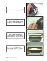
Page 7: ...Remove the developer roller end plates from each side of the toner hopper Fig 24 25 Remove the developer roller from the toner hopper Fig 25 Clean the roller with compressed air and set aside for reassembly 26 Remove two screws that secure the doctor blade Fig 26 Remove the doctor blade and clean with compressed air Fig 24 Fig 25 Fig 26 ...

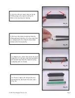
Page 8: ...e developer roller housing with one screw 29 Clean all components thoroughly with compressed air Reassemble toner hopper in reverse order Fill the hopper with the correct gram load of toner Fig 29 30 Remove the drum axle from the small gear end of the drum remove the drum from the waste bin Fig 30 During reassembly insert the drum axle through the opposite end of the drum large gear This will prev...

Page 9: ...tes from the PCR and foam roller Fig 32 Clean the PCR use compressed air to clean the foam roller and set aside for reassembly 33 Remove two screws that secure the wiper blade Fig 33 Remove the wiper and clean all residual toner from the waste bin using compressed air or vacuum 34 Clean or replace all components and reassemble the drum unit in reverse order Fig 34 Fig 32 Fig 33 Fig 34 ...

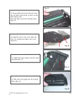
Page 10: ...he waste bin 35 Reassembling the drum and toner unit to the cart frame can be tricky be sure to do the following in order Place the drum unit into the cartridge frame Fig 35 Fig 35 37 Install the tension spring to the tab on the end plate Fig 37 38 Place the toner hopper into the cartridge frame Fig 38 Fig 36 Fig 37 Fig 38 ...

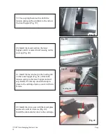
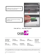
Page 11: ... Fig 40 41 Install the last end cap to the locking tab on the toner hopper Fig 41 Attach the tension spring to the toner hopper and end cap Rotate the end cap down and snap in place to the cartridge frame secure with two screws 42 Install the drive gear with the metal plate and secure with two screws Fig 42 Install the drum shutter door to the cartridge Install the drum shutter door to the Fig 39 ...

Page 12: ...1 800 322 8992 Fax 603 598 4277 Tennessee 800 322 8992 Fax 901 366 9756 Texas 800 322 8992 Fax 972 692 6976 Canada 800 322 8992 Fax 972 692 6976 South America 800 322 8992 International 603 880 1552 Fax 603 386 7575 Illinois 800 322 8992 Fax 972 692 6976 California 800 322 8992 Fax 718 908 7788 North Carolina 800 322 8992 Fax 603 386 7575 Europe Netherlands 011 31 24 388 2233 Fax 011 31 24 355 737...

Reviews: