background image

PLASMA DISPLAY TV

Chassis : 

D62B

Model:

PPM50H3QX/EDC

PLASMA  DISPLAY  TV

C O N T E N T S

Specifications

Alignment and Adjustments

Exploded View and Parts List

Service Item

Schematic Diagrams

1.

2.

3.

4.

5.

SERVICE

Manual

Summary of Contents for PPM42S3

Page 1: ...LASMA DISPLAY TV Chassis D62B Model PPM50H3QX EDC PLASMA DISPLAY TV CONTENTS Specifications Alignment and Adjustments Exploded View and Parts List Service Item Schematic Diagrams 1 2 3 4 5 SERVICE Manual ...

Page 2: ... 1204 6 W x 79 D x 7245 H mm 47 43 W x 3 11 D x 28 5 H inches 43 Kg without stand 50 Inches AC 120V 60Hz AC 100 250V 50 60Hz 490 Watts 1366 H X 768 V RS 232C IN Mini jack RS 232C OUT D SUB 9P VIDEO S VIDEO COMPONENT 1 COMPONENT 2 RGB PC 1 2 DVI External Speaker 10W 10W Audio Output L R RCA VIDEO S VIDEO COMPONENT 1 480i 480p 720p 1080i COMPONENT 2 RGB2 PC IN BNC 5P 480i 1080i VGA XGA RGB1 PC1 D SU...

Page 3: ...1 2 Samsung Electronics MEMO ...

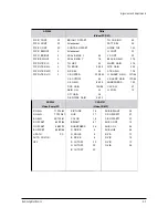
Page 4: ...t turns on and enters service mode If you fail to enter service mode repeat steps 1 and 2 above 2 1 2 Initial DISPLAY State of SERVICE MODE 2 1 2 A OSD DISPLAY 2 1 2 B Button Operations in SERVICE MODE 1 VSP9437 1 9 CXA2101 2 VSP9437 2 10 LOGIC 3 FLI2300 11 TP LOG ASI 4 ASI500 1 12 Option 5 ASI500 2 13 CheckSum 0000 6 DNIe 14 Reset 7 AD9888 8 CXA2151 Release 2003 07 12 T_NEW 50MWW_1001 Menu UP DOW...

Page 5: ...M 01 PAL 01 SECAM 27 NTSC 01 NTSC 4 43 27 PAL 60 27 NR 01 V PEAKING 16 HPLL SPEED 00 PAL 01 SECAM 27 NTSC 01 PAL AV 01 SECAM AV 27 NTSC AV 01 Y DELAY 05 C DELAY 12 CONTRAST 95 BRIGHTNESS 185 SATURATION 110 R CONTRAST 32 30 G CONTRAST 32 30 B CONTRAST 32 30 R BRIGHTNESS 0 G BRIGHTNESS 0 B BRIGHTNESS 0 TEXT ALPHA 1 TEXT THRESHOLD 7 FILTER ML 0 FILTER MR 0 FILTER FR 0 FILTER MC 16 FILTER UC 0 FILTER ...

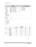
Page 6: ...AIN 64 75 DCE GAIN 190 96 SKIN ON 00 CTI GAIN 08 DE NOISE GAIN 08 10 TH CORING 02 PATT SEL 00 NOISE TH3 100 H CONT 32 V CONT 32 BLACK GAIN 375 WHITE GAIN 375 WTE GAIN 300 CTE GAIN 176 H SHARP GAIN 127 48 V SHARP GAIN 127 48 SHARPNESS 100 CLK DLY 07 H POSI 12 R GAIN 71 128 83 G GAIN 77 122 81 B GAIN 95 128 81 R OFFSET 63 79 64 G OFFSET 66 53 70 B OFFSET 64 82 68 V PATH PC AUTO COLOR OFF PICTURE 16 ...

Page 7: ... 1 APC SET 0 APC VALUE 127 ACTIVE VPOS 12 ACTIVE HPOS 19 VSYNC POS 3 HSYNC POS 32 VSYNC WIDTH 2 HSYNC WIDTH 12 LOG PATTERN 0 LOG HIGH LEVEL 0 LOG LOW LEVEL 0 ASI COLORBAR 0 CXA2151 Data 00 Gam Sel 01 01 CB Gain 07 02 CR Gain 07 03 Y Gain 01 04 V TC 01 IC Video S VHS Component PC DVI SNI Bright 41 44 39 39 Contrast 58 57 67 49 Logic R Gain 140 139 132 134 128 130 130 130 B Gain 122 119 125 120 07 2...

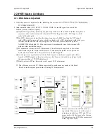
Page 8: ... At this time do not adjust the gain of AD9888 the Highlight W B does not need to be adjusted since its deviation falls within valid distribution range PC adjustment is same as DTV adjustment The offset can be applied to the values obtained through DTV adjustment However additional adjustment is required for Y Cb and Cr of DTV since PC processes R G and B signals cvbs adjustment is performed with ...

Page 9: ...ics 2 2 2 White Balance Coordinates by Mode Pedestal Level Low Light measure point High Light measure point Video Component PC DVI H L x 278 280 280 280 y 285 287 295 295 Y fL 33 34 28 31 L L x 278 280 285 285 y 285 287 295 295 Y fL 1 3 0 6 1 2 1 0 ...

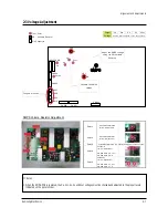
Page 10: ...n Va Ve Vs Vset Notes 1 When the SMPS PCB is replaced the Va Vsc Vs Ve and Vset voltages must be checked and adjusted to the proper levels indicated on the panel sticker SMPS Volume Resistor Adjustment Point 1 Point 2 Point 3 Point 4 Point 5 Point 1 Volume Resistor VR2 for Vs Adjustment Point 2 Volume Resistor VR1 for Va Adjustment Point 3 Volume Resistor VR6 is a Factory Setting Point Don t touch...

Page 11: ...2 8 Samsung Electronics MEMO ...

Page 12: ...TITE RH B M4 L15 ZPC BLK SWR 8 T0081 S N A 12 BN96 00985A ASSY PDP P MODULE M3 S50HW XD03 D66A D3 1 T0044 13 6006 001126 SCREW MACHINE WSP PH M5 L12 NI PLT SWR 4 CCM1 14 BN61 00674A STAND BASE PPM42S3 PPS 2 M0412 15 BN94 00494U ASSY PCB MISC SMPS SPD 50P4HD D66A DAVIN 1 T0124 16 BN96 00999A ASSY PDP P X MAIN BOARD LJ92 00852A S50H 1 T0073 17 BN96 01001A ASSY PDP P Y MAIN BOARD LJ92 00853A S50H 1 T...

Page 13: ...96 01001A ASSY PDP P Y MAIN BOARD LJ92 00853A S50H 1 T0111 BN96 01002A ASSY PDP P Y BUFF UPPER BOARD LJ92 00880 1 T0112 BN96 01003A ASSY PDP P Y BUFF DOWN BOARD LJ92 00881A 1 T0113 BN96 01004A ASSY PDP P E BUFFER BOARD LJ92 00917A S5 1 T0114 BN96 01005A ASSY PDP P F BUFFER BOARD LJ92 00918A S5 1 T0115 BN96 01006A ASSY PDP P G BUFFER BOARD LJ92 00919A S5 1 T0116 BN96 01007A ASSY PDP P H BUFFER BOAR...

Page 14: ...Service Item 4 2 Samsung Electronics MEMO ...

Page 15: ...ound COMPONENT1 Connector S Video Analog Digital Board Video IN IC103 CXA2151Q 5 Schematic Diagrams Samsung Electronics Schematic Diagrams 5 1 5 1 ANALOG 1 This Document can not be used without Samsung s authorization ...

Page 16: ...Schematic Diagrams 5 2 Samsung Electronics FAN PART R246 R247 TILT SENSOR 3D COMB FILTER To DC FAN 50 5 2 ANALOG 2 This Document can not be used without Samsung s authorization ...

Page 17: ...amsung Electronics Schematic Diagrams 5 3 External Speaker MONITOR OUT VIDEO MONITOR OUT SOUND From SMPS Board BD701 1 2 12V_AMP 5 3 ANALOG 3 This Document can not be used without Samsung s authorization ...

Page 18: ...Schematic Diagrams 5 4 Samsung Electronics 74HCT573 74HCT573 5 4 ANALOG 4 This Document can not be used without Samsung s authorization ...

Page 19: ...Samsung Electronics Schematic Diagrams 5 5 5 5 CONTROL AA32 00013B This Document can not be used without Samsung s authorization ...

Page 20: ...Schematic Diagrams 5 6 Samsung Electronics 5 6 DIGITAL 1 PC D SUB DVI SOUND Analog Digital board 42 HD 42 SD Connector 50 63 HD This Document can not be used without Samsung s authorization ...

Page 21: ...msung Electronics Schematic Diagrams 5 7 5 7 DIGITAL 2 PC D SUB BNC Connector ANALOG EDID EPROM From SMPS board 3 OUT LF33CDT IC306 1 IN 2 GND This Document can not be used without Samsung s authorization ...

Page 22: ...Schematic Diagrams 5 8 Samsung Electronics 5 8 DIGITAL 3 This Document can not be used without Samsung s authorization ...

Page 23: ...Samsung Electronics Schematic Diagrams 5 9 5 9 DIGITAL 4 DIGITAL EDID EPROM DVI Connector This Document can not be used without Samsung s authorization ...

Page 24: ...Samsung Electronics 5 10 Schematic Diagrams 5 10 DIGITAL 5 This Document can not be used without Samsung s authorization ...

Page 25: ...Schematic Diagrams Samsung Electronics B12 1204 002105 Flash Memory RS232C IN USER EPROM 256K RS232C OUT From Remote Control board 5 11 DIGITAL 6 This Document can not be used without Samsung s authorization ...

Page 26: ...Samsung Electronics Schematic Diagrams 5 12 5 12 DIGITAL 7 This Document can not be used without Samsung s authorization ...

Page 27: ...5 13 Schematic Diagrams Samsung Electronics LVDS Connector 5 13 DIGITAL 8 This Document can not be used without Samsung s authorization ...

Page 28: ...g Electronics Co Ltd May 2004 Printed in Korea AA82 01607A This Service Manual is a property of Samsung Electronics Co Ltd Any unauthorized use of Manual can be punished under applicable International and or domestic law ...

Reviews: