background image

COLOR QUAD OBSERVATION

SYSTEM

Installation Manual

SSC-21

Summary of Contents for SSC-21WEB

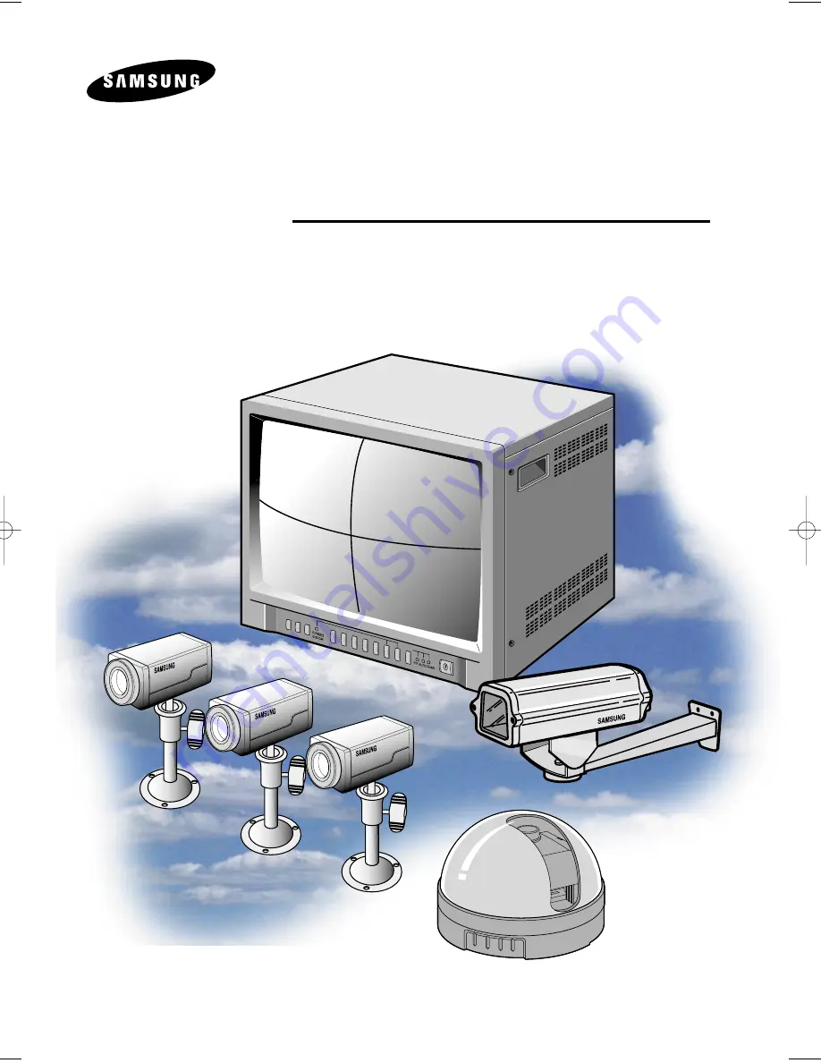
Page 1: ...COLORQUADOBSERVATION SYSTEM Installation Manual SSC 21...

Page 2: ...sons The exclamation point within an equilateral triangle is intended to alert the user to the presence of important operating and maintenance servicing instructions in the literature accompanying the...

Page 3: ...meant for uninterrupted service and that for some specific reason such as the possibility of the loss of an authorization code for a CATV converter is not intended to be unplugged by the user for clea...

Page 4: ...er outlet This is a safety feature If you are unable to insert the plug into the outlet contact your electrician to replace your obsolete outlet Do not defeat the safety purpose of the grounding type...

Page 5: ...overed by the operating instructions as an improper adjustment of other controls may result in damage and will often require extensive work by a qualified technician to restore the monitor to its norm...

Page 6: ...and can radiate radio frequency energy and if not installed and used in accordance with the instruction manual may cause harmful interference to radio communications Operation of this equipment in a r...

Page 7: ...CONFIGURATION 8 1 3 Individual Component Installation 9 1 4 Basic System Installation 19 2 Connecting Peripheral Devices 20 2 1 To connect a PIR Sensor 20 2 2 To connect a VCR 20 3 System Overview 21...

Page 8: ...s If you have purchased only a monitor you should directly purchase every component except accessories STANDARD CAMERA CAMERA HOUSING MOUNTING BRACKET DOME CAMERA CAMERA CABLE CAMERA MOUNT BRACKET ALA...

Page 9: ...unting Bracket SBR 120 1 Housing Assembly Screw 2 hexagonsockethead capscrews L WRENCH 1 PLASTIC ANCHOR 4 Screw 4 for wall attachment Camera Mount Bracket SBR 110 3 Tapping Screw 3 Camera Cable MCB 60...

Page 10: ...unt bracket SBR 110 Choose an installation site that can sufficiently support the weight of the equipments to be installed Attach the camera mount bracket to the wall or ceiling using the supplied thr...

Page 11: ...body of the camera by turning the cover in a counter clockwise direction with one hand while holding the body with the other Connect the camera cable to the camera cable jack on the dome camera then c...

Page 12: ...o location by swiveling the camera PCB board up and down and adjust the focus by turning the lens clockwise and counter clockwise Put the dome cover back on the camera by rotating the cover clockwise...

Page 13: ...ion of the camera onto the CAMERA MOUNT BRACKET Choose an installation site that can sufficiently support the weight of the equipments to be installed Attach the camera mount bracket to the wall using...

Page 14: ...camera position Tighten the handle turning it clockwise and lock the camera in position Connect the camera cable to the camera Specifications Use Indoor Installation Wall or Ceiling Dimensions 52 53...

Page 15: ...mm diameter 45 mm depth and then install and secure the plastic anchors At this time cut away all exposed protrusions Align the housing mount bracket over the plastic anchor holes then firmly fasten t...

Page 16: ...hat the camera may perform safely Installation This section explains how to install the camera within the HOUSING and how to install the CAMERA HOUSING MHG 110 onto the MOUNTING BRACKET SBR 120 Loosen...

Page 17: ...OUSING Slide the spring washer and plain washer onto the supplied screw 1 4 20UNF then install the camera onto the camera housing plate Insert one end of the cable to CABLE GROUND PG 13 5 then pull th...

Page 18: ...hen set up CAMERA MOUNTING PLATE and the camera in the appropriate place inside the HOUSING Slide the camera body into the housing body in the direction of arrow then install the two supplied screws t...

Page 19: ...EW located at the bottom of WALL MOUNT BRACKET by turning it counter clockwise then position the CAMERA HOUSING by tilting and swiveling and tighten the hexagonal groove SCREW by turning it clockwise...

Page 20: ...to CAMERA IN on the back of the monitor At this time select the numbers and sequence of cameras Connect the camera you wish to install as shown below Connect the power cord between the monitor and the...

Page 21: ...r signal is NO Normal Open Sensor is not supplied Sold separately 2 2 Connecting to a VCR Connect the VCR as shown above Connect Time lapse VCR s Alarm in jack to Monitor Alarm out jack Color Gray Con...

Page 22: ...rotation of channels Selectable dwell time Alarm output connectivity to alarm system or fire detection system Alarm Buzzer On Off and Sound Select features Auto detection of camera connections and vi...

Page 23: ...e vicinity of the camera location and transmitting to the monitor Camera fitting groove Enables the camera to be fixed onto the bracket You may install it either above or below the camera if necessary...

Page 24: ...out the main function Handle with care Camera Frame Frame that provides support to the camera Dome Cover Clear plastic cover that protects the camera Take care not to scratch the cover 6Pin modular j...

Page 25: ...een will not be turned off ALARM RESET This key enables the cancellation of all Alarms after one or more alarms have been detected Clears the alarm and turns off the buzzer VOLUME Enables the control...

Page 26: ...nd PIP MODE this is used to store changes made to preset values as well as to select or cancel the function CHANNEL SELECT When switching to SINGLE MODE Used when switching to SINGLE MODE from QUAD AU...

Page 27: ...cancel the Freeze feature MODE Enables the Display Mode to switch sequentially in the order of QUAD AUTO PIP respectively Corresponding LED lights are lit sequentially in the order of QUAD AUTO PIP ea...

Page 28: ...anel AC IN Power input jack CAMERA IN A 6 Pin Modular jack used for video input and camera power input Pin Configuration of the 6 Pin Connector is as follows PINNUMBER SPEC 1 ALARM_IN 2 VIDEO_IN 3 GND...

Page 29: ...m occurs Alarm signal will output for the duration of Alarm Hold time ALARM RESET If Alarm Reset Key is turned On Alarm Reset signal has on output At this time Alarm mode is cancelled When connecting...

Page 30: ...a keys to locate the character to be inputted Characters available for input are shown at the bottom of the screen as Character table Maximum of 8 characters can be entered for each channel Press the...

Page 31: ...lay returns to the Main Menu screen 3 Display Mode Setup Use this to display date time and Channel Title display as well as to set the quadrant border color Go to TYPE a a then use the a a keys to sel...

Page 32: ...50 TINT 50 SHARP 50 EXIT PRESET 5 ALARM BUZZER Setup Use this to select audio output channel for alarm and video loss occurrence while in the System operation Setup and Quad modes Use the a a keys a a...

Page 33: ...he full screen When more than one alarm occurs the monitor will automatically switch to Quad Display mode and the letter A will be displayed at the bottom left quadrant of the corresponding channels W...

Page 34: ...ss the ZOOM key again to return to the previous mode 3 Freeze Feature Use the Freeze Feature while in the Single or Quad mode In the Single mode you can view a still picture by pressing the FREEZE key...

Page 35: ...deo Signal Composite 1Vp p Video Signal 0 714Vp p Sync Signal 0 286Vp p Color subcarrier frequency sync range 3 579545MHz 500Hz at room temperature Range of horizontal sync frequency HSF 15 75KHz 500H...

Page 36: ...1 0Vp p 75ohm composite S N Ratio 50 dB Minimum Object Illumination 2lux F2 0 50 IRE Gamma Correction 0 45 I O Connectors A C input Video outputs MODULAR CABLE 60ft Lens Focal Length f 3 8mm Relative...

Page 37: ...350 TV Lines Signal Output VBS 1 0Vp p 75ohm composite S N Ratio 50 dB Minimum Object Illumination 2lux F2 0 50 IRE Gamma Correction 0 45 I O Connectors A C input Video outputs MODULAR CABLE 60ft Len...

Page 38: ...Memo 37...

Page 39: ...Memo 38...

Page 40: ...Part No AA68 02504A Printed in Korea Samsung CCTV dba GV1 1621 West Crosby Suite 104 Carrollton TX 75006 PHONE 866 492 8246...

Reviews: