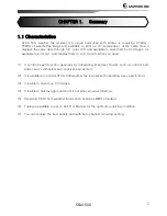
background image


SFAX-500


CHAPTER 1.Summary 

1.1


C

HARACTERISTICS

.....................................................................................5
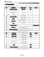
 

1.2


C

OMPOSITIONS

.........................................................................................6


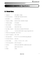
CHAPTER 2.Specification 

2.1


N

ORMAL 

S

PEC

. ........................................................................................7


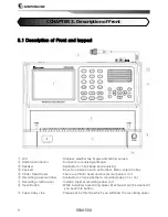
CHAPTER 3.Front part description 

3.1


D

ESCRIPTION OF 

F

RONT AND KEYPAD

............................................................... 8


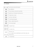
3.1.1 Keypad........................................................................................... 9
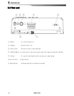
 

3.2


R

EAR PART

........................................................................................... 10
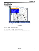
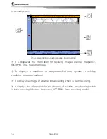
 

3.3


LCD


D

ISPLAY

........................................................................................ 11
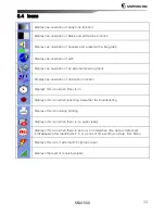
 

3.4


I

CONS

................................................................................................ 13
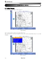


CHAPTER 4.MENU 

4.1


I

NITIAL 

D

ISPLAY

...................................................................................... 14
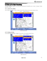
 

4.2


S

ET UP FOR 

S

TART 

R

ECEIVING

..................................................................... 15


4.2.1 Automatic Mode .............................................................................15


4.2.2 Manual Mode .................................................................................15


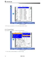
4.2.3 Forced Mode..................................................................................16


4.2.4 Timer Mode....................................................................................17


4.3


C

HANNEL 

S

ETUP

..................................................................................... 19


4.3.1 Zone .............................................................................................20


4.3.2 Station ..........................................................................................20


4.3.3 Channel.........................................................................................21


4.3.4 Frequency .....................................................................................21


4.4


T

IMER 

S

ETUP

........................................................................................ 23


4.4.1 Edit...............................................................................................23


Summary of Contents for SFAX-500

Page 1: ...F FRONT AND KEYPAD 8 3 1 1 Keypad 9 3 2 REAR PART 10 3 3 LCD DISPLAY 11 3 4 ICONS 13 CHAPTER 4 MENU 4 1 INITIAL DISPLAY 14 4 2 SET UP FOR START RECEIVING 15 4 2 1 Automatic Mode 15 4 2 2 Manual Mode 15 4 2 3 Forced Mode 16 4 2 4 Timer Mode 17 4 3 CHANNEL SETUP 19 4 3 1 Zone 20 4 3 2 Station 20 4 3 3 Channel 21 4 3 4 Frequency 21 4 4 TIMER SETUP 23 4 4 1 Edit 23 ...

Page 2: ... STATION 30 5 5 IMAGE BACKUP 31 5 6 DELETE ALL IMAGES 32 5 6 DELETE ALL IMAGES 32 5 7 SIMULATION 33 CHAPTER 6 SYSTEM SETUP 6 1 LCD KEY BOARD BACKLIGHT 35 6 2 KEY BEEP SETUP 36 6 3 NO PAPER ALARM 36 6 4 DISPLAY SETUP 37 6 4 1 Screen color Mode 37 6 4 2 Language setup 38 6 5 TIME SETUP 39 6 5 1 Date Time setup 39 6 5 2 GPS Time Offset Setup 40 6 6 C MMUNICATION SETUP 41 O 6 6 1 NMEA 0183 41 6 6 2 Ex...

Page 3: ...YSTEM VERSION 48 CHAPTER 7 IMAGE SETUP 7 1 INITIAL SCREEN 49 7 2 ZOOM I 49 N 7 3 ZOOM OUT 50 7 4 ROTATE 50 7 4 1 Counterclockwise 51 7 4 2 Clockwise 51 7 5 LOCK 52 7 6 PHASE 53 7 7 SYNC 55 7 8 EDIT COLOR 56 7 9 REVERSE COLOR 57 7 10 COPY IMAGE 58 7 11 DELETE IMAGE 59 7 12 PRINT 60 CHAPTER 8 SETUP AND HOW TO USE PRINTER 8 1 I STALLATION 62 N 8 2 H W TO REPLACE THE PAPER 64 O ...

Page 4: ...10 3 2 Power 72 10 3 3 Receiver 72 CHAPTER 11 Appendix 11 1 MENU TREE 73 11 1 1 Menu 73 11 1 2 System Setup 74 11 1 3 Image Menu 75 11 2 WORLD MAJOR WEATHER FAX FREQUENCY 76 11 2 1 ASIA 76 11 2 2 SOUTH AMERICA 79 11 2 3 NORTH AMERICA 79 11 2 4 PACIFIC OCEAN BASIN 82 11 2 5 EUROPE 83 11 2 6 AFRICA 84 11 3 EXTERNAL DIAGRAM 85 11 4 EXTERNAL CONNECTION DIAGRAM 86 11 5 INTERNAL C NNECTION DIAGRAM 87 O ...

Page 5: ...you need 1 It controls each function generally by integrating important circuits such as control part power part synthesizer part receiver part and etc 2 It is available to control SFAX 500 weather fax receiver with operating a key pad in front 3 It is able to save max 30 images 4 It is able to display again and print it out what you saved before 5 Receiving DATA from weather information centre as...

Page 6: ...M4 X12 3 5 Fuse 5A L 20mm 2 6 Instruction Manual 1 Language select 7 Dust cover For SFAX 500 weather fax Protection cover 1 8 Thermal recording paper I D 12 O D 40 W 260mm Length of paper Abt 12m 1Roll chart 1 Basic composition form NO Description Model Number Unit Remark 1 Whip Antenna DAF 30R 1Set FAX only 2 Antenna Cable MP 20M RG58 0 P N 574 0150 02 1Set 1 Antenna Coaxial cable RG 58 U P N 568...

Page 7: ...E o Screen display Black White Gray o Recording System Solid state recording by thermal head o Paper I D 12 O D 40 W 260mm Length of paper Abt 12m o Effective recording width 252 0 0 2mm o Index of cooperation 576 or 288 o Scanning speed 60 90 120 180 240 SPM Scanning Minutes o Scanning resolution 8dots mm o Power voltage DC 22V 31V 24V 10 30 o Current consumption Min 0 5A Max 5A o Antenna WHIP An...

Page 8: ...s for operation such as Number Menu direction key Printer Head Cover There are Printer head and printer mechanism in it Recording paper window Available to check whether a recording paper in or not Recording cradle cover Install a thermal recording paper in it Open Button While installing a recording paper Mechanism will be opened if you push this button Paper Array Line Please set by this line wh...

Page 9: ... Switch for Auto or Manual of receiving mode Put gray tone on screen Use when control phase For feeding printing paper Move to channel setting menu Print received images For adjust volume For adjust tuning Move the cursor you can adjust the screen brightness by up and down arrows upon Receive mode For input setting ...

Page 10: ...wer 24V Connect to Power to the equipment Terminal Block It is used for B K external reception input GPS input and extra RS 422 232 SD Card It is used for inserting SD card for version up or data backup Earth terminal Using for Earth Input Antenna Receiving antenna is connected to this part ...

Page 11: ...solution of LCD is set on 800 X 600 Status display Function display Screen display LCD screen 2 Screen display Displays FAX images 3 Function display Available to select function on MENU 4 Condition display Displays a frequency receiving Mode Date Time and etc ...

Page 12: ...el frequency IOC RPM time receiving mode It displays a condition of equipment Halftone speaker receiving condition antenna condition It displays the image of weather broadcasting which is been receiving It displays the information for the channel of weather broadcasting which is been receiving channel frequency IOC RPM time receiving mode ...

Page 13: ...plays an operation of diminution function Displays this icon when timer is on Displays this icon when receiving a weather fax broadcasting Displays this icon during printing Displays this icon when there is no paper ready Displays this icon when there is an error on time when time data is defective It disappears after inputting G P S or a correct time setting on Date time Menu Displays this icon i...

Page 14: ...4 1 Initial Display 1 Initial display is showed up when power on Initial display 2 You can see Menu screen if you press Menu key 3 You can move cursor with direction key you can see subordinate menu if you press ENTER Menu screen ...

Page 15: ...eiving with selecting one of auto manual forced and timer mode 4 2 1 Automatic Mode If you select Automatic mode it starts to record from the start receiving signal comes Automatic Mode 4 2 2 Manual Mode If you select Manual Mode it starts to record from the phase signal comes Manual Mode ...

Page 16: ... 16 Internal setting IOC means a resolution of Print RPM means Motor speed 4 2 3 Forced Mode If you select Forced Menu it starts to record at once Forced Mode It is the same as Manual Mode for internal setting ...

Page 17: ...de It begins to receive on time user set if you select timer mode Timer mode Timer operating screen You should complete a timer setup in order to use timer mode Refer 4 4 Timer Sepup You can see icon during timer mode operating ...

Page 18: ...SFAX 500 18 2 During Timer Mode standing by automatically it works Clock mode if there s no input more than 1minute During clock mode it goes back to before screen if there s any input ...

Page 19: ...er 4 3 5 Channel setting screen Channel setting internal screen It is available to select Zone Station channel Frequency with Direction key Zone Select Zone among Asia America Pacific Ocean Basin Europe Africa Station Select one in the zone Channel Select a channel available from a station Frequency if you want to select a channel directly you can put the channel address directly with Number key ...

Page 20: ...1 Zone Please select Zone where you are among Pacific Atlantic Indian Mediterranean sea Persia Zone setting 4 3 2 Station Select Station Nation in order to receive weather fax broadcasting in your zone Station setting ...

Page 21: ...e of the channels of station which user selected It is automatically connected to the channel which is good for reception condition Channel setting 4 3 4 Frequency Set Frequency and please put frequency address directly Frequency setting ...

Page 22: ...SFAX 500 22 4 3 5 Direct channel setting This function is select channels directly with keypad Channels setting ex The initial number in the box is channel number ...

Page 23: ...g data automatically on the time what user set Timer setting 4 4 1 Edit If you select Timer Setup you will move this page as below Timer setting screen You can select multi ply when time is different When off is on the setting screen Timer mode is not working ...

Page 24: ...low Timer setting Set Zone Station Channel Frequency the same as channel setting IOC Speed means resolution for image receiving and printing speed Start End time Set a start time and end time for receiving data On Off select timer on or timer off Save Exit Save setting data go back to Menu list ...

Page 25: ...500 25 CHAPTER 5 FAX MENU 5 1 Print User can set print method and darkness for printing 5 1 1 Print Method setup User can select one of the modes Auto manual and timer if print method is selected Print menu ...

Page 26: ...e receiving image desired by user If Auto is selected all of the receiving images are printed If Auto on Timer mode is selected the receiving images in timer mode are printed automatically 5 1 2 Darkness setup Darkness is adjusted over 10 100 by using direction button set up Darkness ...

Page 27: ...t Attenuation External receiver and Active antenna related to receiving Menu of receiver 5 2 1 Attenuation setup If the RX signal is strong user can set up attenuation 20Db Attenuation Icon is displayed when the function of Attenuation is operated ...

Page 28: ...ternal receiver setup User can set the status of external receiver External receiver Icon is displayed when external receiver is operated 5 2 3 Active Antenna setup User can set the status of active antenna Active antenna ...

Page 29: ...eceiving signal selected to black or grey tone color is transacted 1 In case of setting Halftone Icon on the display will be changed Halftone ON Halftone OFF Icon means Grey tone 16 darkness is set Icon means Black tone 2 darkness is set ...

Page 30: ...It allows user to set the desired station Menu of station Picture of Edit station Set Private in Zone Set Private in Staion For Channel select the channel desired User can set Call Sign at user s option Set Frequency to be received ...

Page 31: ...up In case of selection of Manual images can be saved over 30 images in memory If the saved images exceed 30 the saved images are deleted from first image It can not be saved in SD card In case of selection of Auto internal memory is same as Manual mode All the RX images are saved in SD card automatically ...

Page 32: ...0 32 5 6 Delete All Images Check if user delete all the save images or not Picture of Delete all Images Check it again before deleting all images Before deleted all images It can not be restored after deleted ...

Page 33: ...SFAX 500 33 5 7 Simulation It is the function of testing of operation without actual communication Simulation Picture of Simulation ...

Page 34: ...SFAX 500 34 Picture of Simuation In case of simulation SIM will be showned ...

Page 35: ...TER 6 SYSTEM SETUP 6 1 LCD KEY board Backlight User can adjust the brightness of LCD and keyboard backlight LCD Key backlight It can be adjusted by using right left direction key Picture of adjustment LCD Key backlight ...

Page 36: ... 500 36 6 2 Key Beep setup User can set key beep which is happened when pressed key button Setup key beep 6 3 No Paper Alarm User can set No Paper Alarm for alarm sound when there is no paper No paper alarm ...

Page 37: ...age 6 4 1 Screen color Mode User can set the screen color of outside of image to Daylight mode or Night mode Screen color Mode Daylight Mode Night Mode In Daylight Mode the outside of the image is shown as white color In Night Mode the outside of the image is shown as dark grey color ...

Page 38: ...SFAX 500 38 6 4 2 Language setup User can select language to English or Korean Language Setup language ...

Page 39: ...SFAX 500 39 6 5 Time Setup User can set the time deviation of the unit s time and GPS input 6 5 1 Date Time setup User can set a current date time of the unit Date time Date time setup ...

Page 40: ...SFAX 500 40 6 5 2 GPS Time Offset Setup User can set a function to offset the GPS time differences Menu of GPS Time Offset GPS Time Offset Setup ...

Page 41: ...n set communication environment by using external connection terminal Communication Setup 6 6 1 NMEA 0183 NMEA 0183 Setup NMEA 0183 is port for receiving GPS signal Set up the communication speed of external device on the same speed as SFAX 500 ...

Page 42: ...olt of the back side After removed the connectors of keyboard PCB tip back the keyboard PCB If user pull the switch of the hole of CPU shield to downward direction the RS 232 communication will be set If user pull it to upward direction the RS 422 communication will be set RS 232 to be set when taking out the goods Set up the communication speed of external device on the same speed as SFAX 500 In ...

Page 43: ...SFAX 500 43 6 7 Test Setup User can test RX print and GPS input of the unit Test Mode Test Menu ...

Page 44: ...f the unit is working properly RF Test 6 7 2 Print Test This is the function to check the status of operation of printer Print Test 6 7 3 View GPS Input This is the function to check the RX condition of GPS signal in case of connecting external GPS device GPS Test ...

Page 45: ...the unit and the user s setup data Menu before initialization of memory Menu before initialization In clear memory mode it is available to initialize by selecting fax image or user setup In case of initialization of fax image both external internal memories are deleted Before initialization check it again if the initialization is required The deleted data can not be restored ...

Page 46: ...oad Default Setup It makes the setup condition return to initial condition Load Default Setup Load Default Setup Before initialization check it again if the initialization is required The deleted data can not be restored ...

Page 47: ...grade The screen of Software Upgrade Execute RUN after inserting the SD card with the software for upgrading to the socket Turn the unit off after checking the completion of software update If the power is off for upgrading the software it causes a breakdown 2G SD Memory is not supported SCHC memory is supported ...

Page 48: ...SFAX 500 48 6 9 System Version This is the function to check a version of unit System Version The Screen of System version ...

Page 49: ...eys Initial Screen 2 If ENTER key is pressed the image is selected 3 If MENU is pressed image setup menu is displayed 4 User can move a cursor by selecting Direction key and the selected menu is executed if ENTER is pressed 7 2 Zoom In This is a function to see the enlarged image selected Zoom In ...

Page 50: ...e reduced image selected Zoom Out 7 4 Rotate This is a function to rotate the selected image Rotate User can rotate the image to clockwise direction or counterclockwise direction If user select Exit after rotating the image the image is saved automatically ...

Page 51: ...SFAX 500 51 7 4 1 Counterclockwise Select Counterclockwise the image rotate to the left Rotate Counterclockwise 7 4 2 Clockwise Select Clockwise the image rotate to the right Rotate Clockwise ...

Page 52: ...SFAX 500 52 7 5 Lock Function for protecting from the saved image delete Lock Lock Image Show the Lock Icon on Image when the image lock function work ...

Page 53: ...the Phase function can adjust PHASE MISMATCHING when it will be happened 1 Select the button on the keypad or Phase on Menu Phase Image 2 Check the location of DEAD SECTOR by graduated ruler and input the graduated ruler number with arrow button or keypad Phase Setup Image The sphere of value can be changed from 0 to 31 and DEAD SECTOR location can be chaged by the value ...

Page 54: ...SFAX 500 54 Phase Setup confirm image Adjusted Phase Image ...

Page 55: ...n DEAD SECTOR slants Sync Menu 1 Can slant dynamic climate by Slant to the right Slant to the left The adjustment sphere can control from200 to 200 Use button on the keypad increase number of sync and the image slant to the left Use button on the keypad decrease number of sync and the image slant to the right ...

Page 56: ...SFAX 500 56 7 8 Edit Color Edit the saved image s background color Edit Color 1 Black background and gray background Monochrome background Gray Background Don t change the left top icon as like FAX Menu ...

Page 57: ...SFAX 500 57 7 9 Reverse Color Reverse color image on display Reverse Color Menu Reversed Color Image ...

Page 58: ...SFAX 500 58 7 10 Copy image Copy the received image to SD Card Copy Image Menu Copy Image Display The image will be saved as GIF file ...

Page 59: ...7 11 Delete Image Function for deleting the select image Delete Menu 1 Check again to delete or not before deleting image Delete Image 2 Select Yes and then delete the image the deleted image never can be restored ...

Page 60: ...X 500 60 7 12 Print Function for printing received image printing mode printing Display When use print fuction icon is appear and do process of printing When doing print also choose image and reserve print ...

Page 61: ...SFAX 500 61 reservation display Printing Cancel If cancel printing all reserved image also will be canceled too ...

Page 62: ...FAX 500 62 Chapter 8 USAGE of Printer and Installation 8 1 Installation 1 fix on the installation panel with M5 10mm pararel 2 Push SFAX 500 to arrow direction 3 Open print head cover by push open button ...

Page 63: ...SFAX 500 63 4 Open a print paper cover 5 Fix on the installation panel with M4 14mm bolt 6 Close a print paper cover ...

Page 64: ...SFAX 500 64 8 2 How to replace the paper 1 Press PUSH button 2 Take empty roll paper out to arrow direction 3 Insert new paper to arrow direction ...

Page 65: ...SFAX 500 65 4 Put the paper under the sensor and pull the paper out 5 Pull the paper out some and close the front cover ...

Page 66: ... and open a print head cover Wipe a heater line by using a soft cloth putting alcohol if there s a line or spot on printed image Do not touch a heater line as the printing quality can be no good Do not touch a heater line after print out as it is hot ...

Page 67: ...SFAX 500 67 9 1 Overview Chapter 9 Circuit Diagram SFAX 500 RF BOARD ...

Page 68: ... SFAX 500 MAIN BOARD SFAX 500 consists front keyboard LCD display receiver synthesizer Control power and printer Power DC 22V 31V 24V 10 30 SFAX 500 68 ...

Page 69: ...SFAX 500 69 9 2 Circuit Description 1 Receiver Reception Block Diagram 2 Local Synthesizer Synthesizer Block Diagram ...

Page 70: ...0 3 Power Circuit Power Circuit Diagram Power circuit Power circuit receives DC24V and supplies 24V through a protection and regulated voltage circuit Main Power Circuit Protection and Sensor Circuit are contains ...

Page 71: ...ed Please be aware of matters to be attended as below before inspection and maintenance to avoid improper maintenances 10 2 Measuring Instrument z This device is designed accordingly to international wireless communication laws and measuring instruments for inspection and maintenance is needed to be inspected and tested by an authorized agency For daily inspection and maintenance following measuri...

Page 72: ...and receiver is proper or not 10 3 2 Power z If there is no display even though the power is on following are needed to be checked 1 Whether fuse is disconnected or not The rated current of fuse is 5A 2 Whether the power connector is properly connected or not If the polarity of power is opposite the device will not work 3 Check the voltage in the power supply connector If it is between DC 22 31V i...

Page 73: ...SFAX 500 73 Chapter 11 Appendix 11 1 MENU TREE 11 1 1 Menu ...

Page 74: ...SFAX 500 74 11 1 2 System Setup ...

Page 75: ...SFAX 500 75 11 1 3 Image Menu ...

Page 76: ...S FREQUENCIES TIME RPM IOC BAF6 5526 9 kHz 120 576 BAF36 8121 9 kHz 120 576 BAF4 10116 9 kHz 120 576 BAF8 14366 9 kHz 120 576 BAF9 16025 9 kHz 120 576 BAF33 18236 9 kHz 120 576 BEIJING PEKING CHINA CALL SIGNS FREQUENCIES TIME RPM IOC 3SD 8461 9 kHz 120 576 3SD 12831 9 kHz 120 576 3SD 16903 9 kHz 120 576 ...

Page 77: ...C 148 kHz ALLBROADCAST TIMES 90 576 TAIPEI REPUBLIC OF CHINA CALL SIGNS FREQUENCIES TIME RPM IOC BMF 4616 kHz 120 576 BMF 8140 kHz 120 576 BMF 13900 kHz 120 576 BMF 18560 kHz 120 576 SEOUL REPUBLIC OF KOREA CALL SIGNS FREQUENCIES TIME RPM IOC HILL2 3585 kHz 1200 0000 UTC 120 576 HILL2 5857 5 kHz ALLBROADCAST TIMES 120 576 HILL2 7433 5 kHz ALLBROADCAST TIMES 120 576 HILL2 9165 kHz ALLBROADCAST TIME...

Page 78: ...ROADCAST TIMES JJC 12745 5 kHz ALLBROADCAST TIMES JJC 16971 kHz ALLBROADCAST TIMES JJC 17069 6 kHz ALLBROADCAST TIMES JJC 22542 kHz ALLBROADCAST TIMES 9VF 252 16035 kHz 0740 1010 1415 1815 9VF 252 17430 kHz 0740 1010 1415 1815 NORTHWOOD UNITED KINGDOM PERSIAN GULF CALL SIGNS FREQUENCIES TIME RPM IOC GYA 6834 kHz 1800 0800 UTC 120 576 GYA 12390 kHz ALLBROADCAST TIMES 120 576 GYA 18261 kHz 0800 1800...

Page 79: ...IES TIME RPM IOC CBV 4228 kHz ALLBROADCAST TIMES 120 576 CBV 8677 kHz ALLBROADCAST TIMES 120 576 CBV 17146 4 kHz ALLBROADCAST TIMES 120 576 11 2 3 NORTH AMERICA HALIFAX NOVA SCOTIA CANADA CALL SIGNS FREQUENCIES TIME RPM IOC CHF 122 5 kHz ALLBROADCAST TIMES 120 576 CHF 4271 kHz ALLBROADCAST TIMES 120 576 CHF 6496 4 kHz ALLBROADCAST TIMES 120 576 CHF 10536 kHz ALLBROADCAST TIMES 120 576 CHF 13510 kH...

Page 80: ...2100 2330 UTC 120 576 SYDNEY NOVA SCOTIA CANADA CALL SIGNS FREQUENCIES TIME RPM IOC VCO 4416 kHz 1121 1741 UTC 120 576 VCO 6915 1 kHz 2200 2331 UTC 120 576 INUVIK CANADA CALL SIGNS FREQUENCIES TIME RPM IOC VFA 8457 8 kHz 120 576 KODIAK ALASKA U S A CALL SIGNS FREQUENCIES TIME RPM IOC NOJ 2054 kHz ALLBROADCAST TIMES 120 576 NOJ 4298 kHz ALLBROADCAST TIMES 120 576 NOJ 8459 kHz ALLBROADCAST TIMES 120...

Page 81: ...356 UTC 120 576 NOW ORLEANS LOUISANA U S A CALL SIGNS FREQUENCIES TIME RPM IOC NMG 4317 9 kHz ALLBROADCAST TIMES 120 576 NMG 8503 9 kHz ALLBROADCAST TIMES 120 576 NMG 12789 9 kHz ALLBROADCAST TIMES 120 576 NMG 17146 4 kHz 1200 2045 UTC 120 576 BOSTON MASSACHUSETTS U S A CALL SIGNS FREQUENCIES TIME RPM IOC NMF 4235 kHz 0230z 1028z 120 576 NMF 6340 5 kHz ALLBROADCAST TIMES 120 576 NMF 9110 kHz ALLBR...

Page 82: ... 120 576 VMC 11030 kHz ALLBROADCAST TIMES 120 576 VMC 13920 kHz ALLBROADCAST TIMES 120 576 VMC 20469 kHz 1900 0900 120 576 WILUNA AUSTRALIA CALL SIGNS FREQUENCIES TIME RPM IOC VMW 5575 kHz 1100 2100 120 576 VMW 7535 kHz ALLBROADCAST TIMES 120 576 VMW 10555 kHz ALLBROADCAST TIMES 120 576 VMW 15615 kHz ALLBROADCAST TIMES 120 576 VMW 18060 kHz 2100 1100 120 576 ...

Page 83: ...2145 0500 120 576 HONOLULU HAWAII U S A CALL SIGNS FREQUENCIES TIME RPM IOC KVM70 9982 5 kHz 0519 1556 120 576 KVM70 11090 kHz ALLBROADCAST TIMES 120 576 KVM70 16135 kHz 1719 0356 120 576 11 2 5 EUROPE ATHENS GREECE CALL SIGNS FREQUENCIES TIME RPM IOC SVJ4 4481 kHz 120 576 SVJ4 8105 kHz 20 576 MURMANSK RUSSIA CALL SIGNS FREQUENCIES TIME RPM IOC RBW41 5336 kHz RBW41 6445 5 kHz ALLBROADCAST TIMES RB...

Page 84: ...LL SIGNS FREQUENCIES TIME RPM IOC GYA 2618 8 kHz 2000 0600 UTC 120 576 GYA 4610 kHz ALLBROADCAST TIMES 120 576 GYA 8040 kHz ALLBROADCAST TIMES 120 576 GYA 11086 5 kHz 0600 2000 UTC 120 576 11 2 6 AFRICA CAPENAVAL SOUTH AFRICA CALL SIGNS FREQUENCIES TIME RPM IOC ZSJ 4014 kHz 16Z 06Z WHEN AVILABLE 120 576 ZSJ 7508 kHz ALLBROADCAST TIMES 120 576 ZSJ 13538 kHz ALLBROADCAST TIMES 120 576 ZSJ 18238 kHz ...

Page 85: ...SFAX 500 85 11 3 External Diagram ...

Page 86: ...SFAX 500 86 11 4 External Connection Diagram ...

Page 87: ...SFAX 500 87 11 5 Internal Connection Diagram ...

Reviews: