background image

May 22, 2017
©  S&C Electric Company 2011-2017, all rights reserved

Instruction Sheet  461-500

S&C TripSaver

®

 Dropout Recloser

Outdoor Distribution (15 kV and 25 kV)

Table of Contents

Section  

 Page

Section  

  Page

Introduction

Qualified Persons   .  .  .  .  .  .  .  .  .  .  .  .  .  .  .  .  .  .  .  .  .  .  .  .  .  .  .  .  .  . 2
Read this Instruction Sheet    .  .  .  .  .  .  .  .  .  .  .  .  .  .  .  .  .  .  .  .  .  . 2
Retain this Instruction Sheet  .  .  .  .  .  .  .  .  .  .  .  .  .  .  .  .  .  .  .  .  .  . 2
Proper Application  .  .  .  .  .  .  .  .  .  .  .  .  .  .  .  .  .  .  .  .  .  .  .  .  .  .  .  .  .  . 2
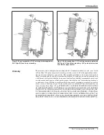
Warranty   .  .  .  .  .  .  .  .  .  .  .  .  .  .  .  .  .  .  .  .  .  .  .  .  .  .  .  .  .  .  .  .  .  .  .  .  . 3

Safety Information

Understanding Safety-Alert Messages   .  .  .  .  .  .  .  .  .  .  .  .  .  . 4
Following Safety Instructions    .  .  .  .  .  .  .  .  .  .  .  .  .  .  .  .  .  .  .  .  . 4
Replacement Instructions and Labels  .  .  .  .  .  .  .  .  .  .  .  .  .  .  . 4
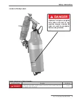
Location of Safety Label     .  .  .  .  .  .  .  .  .  .  .  .  .  .  .  .  .  .  .  .  .  .  .  . 5

Safety Precautions

   .  .  .  .  .  .  .  .  .  .  .  .  .  .  .  .  .  .  .  .  .  .  .  .  .  .  .  .  . 6

Packing and Inspection

Packing   .  .  .  .  .  .  .  .  .  .  .  .  .  .  .  .  .  .  .  .  .  .  .  .  .  .  .  .  .  .  .  .  .  .  .  .  .  . 7
Inspection   .  .  .  .  .  .  .  .  .  .  .  .  .  .  .  .  .  .  .  .  .  .  .  .  .  .  .  .  .  .  .  .  .  .  .  . 7
Handling   .  .  .  .  .  .  .  .  .  .  .  .  .  .  .  .  .  .  .  .  .  .  .  .  .  .  .  .  .  .  .  .  .  .  .  .  . 7
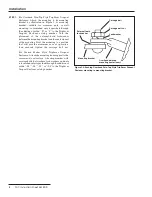
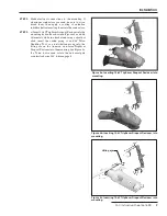
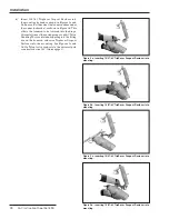
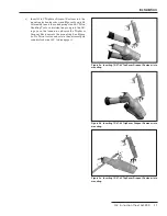
Installation

   .  .  .  .  .  .  .  .  .  .  .  .  .  .  .  .  .  .  .  .  .  .  .  .  .  .  .  .  .  .  .  . 8
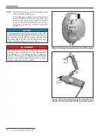
Operation

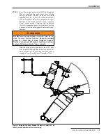
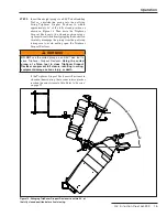
If TripSaver Dropout Recloser Has Dropped Out    .  .  .  .  . 14
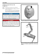
If Line Work Is to Be Performed Downstream  

of TripSaver Dropout Recloser   .  .  .  .  .  .  .  .  .  .  .  .  .  .  .  .  . 16

Operation Counter    .  .  .  .  .  .  .  .  .  .  .  .  .  .  .  .  .  .  .  .  .  .  .  .  .  .  .  . 17
Service   .  .  .  .  .  .  .  .  .  .  .  .  .  .  .  .  .  .  .  .  .  .  .  .  .  .  .  .  .  .  .  .  .  .  .  .  . 17
Under Ice Conditions    .  .  .  .  .  .  .  .  .  .  .  .  .  .  .  .  .  .  .  .  .  .  .  .  .  . 17
Service Soon Indicator   .  .  .  .  .  .  .  .  .  .  .  .  .  .  .  .  .  .  .  .  .  .  .  .  . 18
Overload Ratings    .  .  .  .  .  .  .  .  .  .  .  .  .  .  .  .  .  .  .  .  .  .  .  .  .  .  .  .  . 18
Contact Position Indicator   .  .  .  .  .  .  .  .  .  .  .  .  .  .  .  .  .  .  .  .  .  .  . 18
Operation with Loadbuster

®

 The S&C Loadbreak  

Tool    .  .  .  .  .  .  .  .  .  .  .  .  .  .  .  .  .  .  .  .  .  .  .  .  .  .  .  .  .  .  .  .  .  .  .  .  . 19

Installation and Operation

Summary of Contents for TripSaver

Page 1: ...Safety Alert Messages 4 Following Safety Instructions 4 Replacement Instructions and Labels 4 Location of Safety Label 5 Safety Precautions 6 Packing and Inspection Packing 7 Inspection 7 Handling 7...

Page 2: ...is Instruction Sheet Thoroughly and carefully read this instruction sheet before installing or operating your S C TripSaver Dropout Recloser The latest version is available online in PDF format at www...

Page 3: ...xpress or implied or arising by operation of law course of dealing usage of trade or otherwise are excluded The only warranties are those stated in Price Sheet 150 and THERE ARE NO EXPRESS OR IMPLIED...

Page 4: ...ns are not followed NOTICE NOTICE identifies important procedures or requirements that can result in product or property damage if instructions are not followed Following Safety Instructions If you do...

Page 5: ...umber DANGER TripSaver may be energized from either side and in any position Always consider all parts live until de energized tested and grounded G 9248 Location of Safety Labels G 9248 E DANGER Trip...

Page 6: ...protective equipment such as rubber gloves rubbermats hardhats safetyglasses andflashclothing in accordance with safe operating procedures and rules 4 SAFETY LABELS AND TAGS Do not remove or obscurean...

Page 7: ...ading to make sure that shipping skids crates and containers listed thereon are present If there is visible loss and or damage 1 Notify the delivering carrier immediately 2 Ask for a carrier inspectio...

Page 8: ...the mounting Pivot the mounting to a position that will provide maximum ease of operation then securely tighten the carriage bolt nut For Branch Feeder Style TripSaver Dropout Reclosers Attachthemount...

Page 9: ...ed be sure to wire brush them then apply a coating of oxidation inhibitorbeforeinsertingthemintotheconnectors STEP 3 a Insert15 kVTripSaverDropoutRecloserintothe mounting by hand as shown in Figures 4...

Page 10: ...rt 15 27 kV TripSaver Dropout Recloser into the mounting by hand as shown in Figures 5a and 5b Ensure that the end of the trunnion slides under the connector bracket as shown in Figure 5d This allows...

Page 11: ...ecloser into mounting c Insert 25 kV TripSaver Dropout Recloser into the mounting by hand as shown in Figures 6a and 6b Alternately insert the curled prong of an S C Talon Handling Tool or a distribut...

Page 12: ...l or a distribu tion prong and verify that it reverts to the AUTO position NOTICE The mode selector handle must be placed in the AUTO position before closing TripSaver Dropout Recloser into the mounti...

Page 13: ...om the pull ring takingcaretoavoidpullingopenTripSaverDropout Recloser WARNING DO NOT use the curled prong on an S C Talon tool to close TripSaver Dropout Recloser Using the curled prong of a Talon to...

Page 14: ...ropout Recloser into the mounting Closing TripSaver Dropout Recloser with the mode selector handle in the NR position may result in the unit tripping open due to inrush current DANGER DO NOT attempt t...

Page 15: ...m the pull ring taking care to avoid pulling open the TripSaver Dropout Recloser WARNING DO NOT use the curled prong on an S C Talon tool to close TripSaver Dropout Recloser Using the curled prong of...

Page 16: ...distribution prong into the mode selector handle and place the handle in the NR position and ensure that the mode selector handle is securely engaged in the metal clip See Figure 13 NOTICE With the m...

Page 17: ...cedure outlined in Step 3 on pages 9 through 11 to the remove TripSaver Dropout Recloser from the cutout mounting Under Ice Conditions Ice hood suffix H1 can be added to increase ice breaking capabili...

Page 18: ...Dropout Recloser rating to be activated e g 30 amperes for the 100K 65T TripSaver Dropout Reclosers Overload Ratings The TripSaver Dropout Recloser overload ratings are as follows Models with 100K an...

Page 19: ...ing operation using the Loadbuster Tool the TripSaver Dropout Recloser can be lifted out of the mounting using a universal pole equipped with a suitable fuse handling fitting such as an S C Talon Fuse...

Page 20: ...proper disengagement When the Loadbuster Tool is properly attached as shown in Figure 20a or 20b a downward pull of the pole to open the TripSaver Dropout Recloser extends the Loadbuster Tool and char...

Page 21: ...S C Instruction Sheet 461 500 21 Operation Figure 20c Incorrect approach Figure 20d Incorrect approach Figure 20b Correct approach Figure 20a Correct approach Never This Never This...

Page 22: ...ut Recloser STEP 4 To open the circuit operate the Loadbuster Tool with a firm steady pull until it is extended to its maximum length See Figure 22 Avoid jerking and hesitation The resetting latch wil...

Page 23: ...lly extended To perform this operation easily and smoothly always roll the Loadbuster Tool so that it rotates in an upward direction STEP 6 To reset the Loadbuster Tool for the next operation hold it...

Page 24: ......

Reviews: