background image

Summary of Contents for SN3308

Page 1: ......

Page 2: ...he following information is in addition to that presented in Chapter 3 of the Pilot s Guide a The indicated strike rate applies only to the visible area of the display Zooming in the map range may cau...

Page 3: ...e pointer should be set to the published front course In software versions 2 10 and later the bottom CDI will automatically reverse sense when the course pointer is more than 90 Deg from the lubber li...

Page 4: ...the SN3308 Pilot s Guide SPN 82001PG B2 90106PG B2 All Chapters Removed references to radar altimeter Color illustrations moved from Appendix 3 to Appendix 2 ARC description changed from 90 to 70 deg...

Page 5: ...eration Chapter 6 Minor clarifications Chapter 7 Revised list of abnormal conditions List of on screen messages moved from Appendix 2 to this chapter Chapter 8 Corrected power input current specificat...

Page 6: ...Pilot s Guide Document No 90106 PG Revision C 82001 PG Revision C Publication Date October 27 1999 SN3308 Navigational Display...

Page 7: ...is manual are available from Sandel Avionics LLC 2401 Dogwood Way Vista CA 92083 Tel 760 727 4900 Fax 760 727 4899 Information in this manual is current as of publication or revision date Specificatio...

Page 8: ...The Effectivity and Errata page a specifically lists the software to which this Pilot s Guide applies b corrects any errors or omissions in this revision of the Pilot s Guide c will be reprinted at t...

Page 9: ...i function display device under Technical Standard Order TSO C 113 Installation of the SN3308 in a type certificated aircraft must be performed in accordance with the Sandel Avionics SN3308 Installati...

Page 10: ...2 1 What is it 1 1 Welcome to the SN3308 Operational and Legal Issues 1 2 Display Areas 2 1 Indicators 2 2 Data Color Coding 2 3 Operational Basics Power up Displays 3 1 Selecting the Data 3 3 Select...

Page 11: ...he Course Pointer 3 9 Auto Slewing the Course Pointer 3 10 Controlling the Display 3 8 Operational Basics Continued ARC View and 360 View 3 8 Centering the Heading Bug or Needle 3 10 Setting the Map R...

Page 12: ...RROW 4 15 DOWN ARROW 4 13 VUE 4 17 Overview 5 1 Internal Database 5 2 Map Controls and Displays 5 2 Map Memories 5 4 Getting Started Example 5 6 Map Setup 5 7 Escaping Map Setup 5 9 Setting Other Item...

Page 13: ...a Map Memory to the Rotation Sequence 5 10 Enhanced Moving Map Features Continued Restoring the Factory Default Map Presets 5 10 Map Auto Range 5 12 Getting the Most From Your SN3308 Using the HSI 6 1...

Page 14: ...NTENTS A P P E N D I X 1 A P P E N D I X 2 W A R R A N T Y ARC View A2 2 360 View with Map A2 3 ARC View with Map A2 4 Illustrations Technology of the SN3308 360 View A2 1 Flags A2 5 Limited Parts Lab...

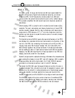
Page 15: ...Welcome to the SN3308 1 C H A P T E R...

Page 16: ...mscope display into one instrument the SN3308 ties together the critical elements of situational awareness And by adding to that a 3 light marker beacon and GPS annunciator displays the SN3308 becomes...

Page 17: ...elines are supplied to the SN3308 by the associated IFR GPS receiver through the receiver s serial data link Supplemental data is intended for positional awareness only and should not be used for prim...

Page 18: ...a two button sequence for example push SHFT SYNC to center the needle This means that the buttons are to be pushed consecutively not held simultaneously This manual will use terms which should be fami...

Page 19: ...Display Overview 2 C H A P T E R...

Page 20: ...s either a 360 degree or a 70 degree ARC view as indicated by the white compass ring The white airplane represents the aircraft s current position The primary display area may also depict the current...

Page 21: ...displayed smaller than normal and close to the edge of the screen The symbol is the course pointer By rotating the Course Select knob you can set the course pointer to the desired course to a VOR nav...

Page 22: ...anumeric data displayed on the SN3308 is color coded as follows 2 3 2 Display Overview C H A P T E R GREEN Stormscope strike data Information associated with the primary VHF NAV1 receiver or NAV2 if i...

Page 23: ...or Moving map waypoints YELLOW Information associated with the cross side NAV receiver NAV2 if in pilot configuration NAV1 if in co pilot configuration Information associated with the cross side GPS b...

Page 24: ...Operational Basics 3 C H A P T E R...

Page 25: ...pproach Power up Displays On initial power up several different messages may be displayed on the SN3308 These messages are displayed along the top of the display Some of the more urgent messages will...

Page 26: ...by replacement of the lamp and resetting of the lamp monitor by your avionics shop TO PERFORM AUTOMATIC LAMP The internal lamp TEST RUN FOR 2 MINUTES monitoring system AT MAXIMUM BRIGHTNESS periodical...

Page 27: ...ges Chapter 7 describes a complete list of both normal and abnormal messages which can be displayed on the SN3308 at any time Selecting the Data Sensor data is data that comes from various devices wit...

Page 28: ...t of the display as a reminder If a valid glideslope signal is also being detected the status message changes to ILS The message is turned off if the VOR receiver is tuned to a normal VOR omni bearing...

Page 29: ...loran as well as nearby airports navaids intersections and airspace from the SN3308 s internal database The map display is controlled by pressing the MAP button to cycle through the different map mem...

Page 30: ...actory Defaults 1 Flight plan waypoints and courselines only 2 Flight plan waypoints and civil airports with runways 3500 ft long 3 Flight plan waypoints and high level and low level VORs Note both th...

Page 31: ...ized with the aircraft s heading A status word in the upper right corner of the SN3308 display is dedicated to the WX 500 In normal operation this status word shows the current strike rate preceded by...

Page 32: ...oximately 70 degrees around the top of the screen Arc view maximizes the display of the ground track ahead of the aircraft and provides the greatest amount of screen area for map data Press VUE to swi...

Page 33: ...eselected To turn off both the map and the Stormscope display simultaneously press and hold the MAP button for at least 1 5 seconds Displaying the Course Pointer The course pointer itself can be remov...

Page 34: ...eceivers such as the King KLN 90B and Garmin GNS 430 support an OBS or HOLD mode which when active will override auto slew Centering the Heading Bug or Needle To rapidly set the heading bug to the air...

Page 35: ...memorize the settings for later use For example your preferred enroute setup might be ARC view with only bearing pointer 1 displayed connected to a VOR navaid Your approach setup might be in 360 degr...

Page 36: ...Button Operations 4 C H A P T E R...

Page 37: ...source selection is accomplished with an external switch See your Aircraft Flight Manual Supplement for more information HOLD No action performed SHFT NAV Displays the GPS mode selection switches and...

Page 38: ...er 307 3 6 307 NAV1 018 ADF1 170 SYNC A B MSG 0 G P S 1 27 5 nm BUR 307 RNG 75nm 250 KT 307 WX N A V V U E M A P B R G N 24 21 W 33 3 6 E 15 12 30 CRQ BUR LAX18 B 30 G P S 1 27 5NM N A V SHFT 1 N 24 2...

Page 39: ...H Controls the display of moving map data Cycles through the map scratchpad and memories HOLD Turns the map display off MAP OFF will be displayed at the top of the screen SHFT MAP Accesses the map set...

Page 40: ...RNG 75nm RNG 75nm 250 KT 307 WX N A V V U E M A P B R G N 24 21 W 33 3 6 E 15 12 30 CRQ BUR LAX18 B SHFT M A P 24 21 S Scratchpad 1 Map Memory 1 2 Map Memory 2 3 Map Memory 3 4 Map Memory 4 C O P Y E...

Page 41: ...to either pointer pushing BRG has no effect HOLD Turns both bearing pointers off SHFT BRG Assigns a nav source including the option of OFF to each of the two bearing pointers Pushing SHFT BRG brings...

Page 42: ...307 3 6 307 NAV1 018 ADF1 170 SYNC A B MSG 0 G P S 1 27 5 nm BUR 307 N A V V U E M A P B R G N 24 21 W 33 3 6 E 15 12 30 CRQ BUR LAX18 B SHFT MSG B R G 21 RNG 75nm 250 KT 307 WX 1 SYNC A B N A V V U...

Page 43: ...FT acts as a shift key permitting access to a selection of sub menus for certain buttons Failure to select a sub menu for 20 seconds or pushing SHFT a second time cancels the sub menu access and retur...

Page 44: ...SHFT SHFT GPS Functions D BAR Course Pointer Auto Slew Settings Map setup functions BRG Pointer Source selection menu Centers CDI When auto slew disabled WX 500 Stormscope functions Copies current scr...

Page 45: ...lected nav source the current radial is chosen as the direct to course information and the CDI needle centers with a TO flag indication If the selected nav source is a GPS or loran this performs the d...

Page 46: ...se pointer to current heading SYNC 15 12 SYNC 15 12 307 3 6 307 NAV1 018 ADF1 170 SYNC A B MSG 0 G P S 1 27 5 nm BUR 307 MAP OFF 250KT MAP OFF 250KT 307 N A V V U E M A P B R G N 24 21 W 33 3 6 E 15 1...

Page 47: ...ters that is made while A is active become part of A Any changes made while B is active become part of B Pushing A B swaps the active screen for the inactive screen Either A or B is displayed at the t...

Page 48: ...6 307 NAV1 018 ADF1 170 SYNC A B MSG 0 G P S 1 27 5 nm BUR 307 N A V V U E M A P B R G N A V M A P B R G N 24 21 W 33 3 6 E 15 12 30 CRQ BUR LAX18 B SHFT ADF1 170 A B E OM 307 3 6 307 SYNC A B MSG 0...

Page 49: ...map range from 1000 nautical miles down to 1 nautical mile The currently selected map range is shown at the top of the display When the bottom of the map range is reached further pushes of have no ef...

Page 50: ...p 4 Zooms in map range 6 307 3 6 307 NAV1 018 ADF1 170 SYNC A B MSG 0 G P S 1 27 5 nm BUR 307 N A V V U E M A P B R G N 24 21 W 33 3 6 E 15 12 30 CRQ BUR LAX18 B SHFT 1000nm 750nm 500nm 2nm 1 5nm 1nm...

Page 51: ...a flight plan or a direct to waypoint is active on the LNAV receiver the map range will auto scale until reaching a setting at which the entire flight plan is visible SHFT UP ARROW If a WX 500 Storms...

Page 52: ...018 ADF1 170 SYNC A B MSG 0 G P S 1 27 5 nm BUR 307 N A V V U E M A P B R G N 24 21 W 33 3 6 E 15 12 30 CRQ BUR LAX18 B SHFT 1nm 1 5nm 2nm 500nm 750nm 1000nm 3 SYNC A B N A V V U E M A P B R G N 24 2...

Page 53: ...compass view and a 70 degree ARC view Note that in the ARC view the location of the aircraft is at the bottom of the display Appendix 2 contains illustrations of 360 degree view and ARC mode view HOL...

Page 54: ...P S 1 27 5 nm BUR 307 RNG 75nm 250 KT 307 V U E N 24 21 W 33 3 6 E 15 12 30 CRQ LAX BUR LAX BUR SHFT NAV1 018 MSG NAV1 018 ADF1 170 ADF1 170 N A V M A P B R G B 307 27 5 nm BUR 307 RNG 75nm 250 KT 30...

Page 55: ...ays if either is turned on A B Switches between two groups of screen settings Allows the pilot to set up two different displays and swap back and forth between them with a single button SYNC Moves the...

Page 56: ...sses sytem sub menu for self test or demo mode No function performed A B A B Copies the current screen settings into the inactive screen setting memory SYNC DTK Performs a course sync i e turns the co...

Page 57: ...Enhanced Moving Map Features 5 C H A P T E R...

Page 58: ...isplay Finally you may store up to four different map configurations and then quickly switch from one to another as appropriate to your phase of flight For instance when cruising at FL180 or higher yo...

Page 59: ...ates are available directly from Sandel Avionics and may be purchased online at www sandel com Newly manufactured units may not contain an internal database when shipped from the factory Your avionics...

Page 60: ...and holding the button auto ranges to the end of the current flight plan SHFT MAP Accesses the map setup function and allows enabling or disabling of various map items 5 3 5 Enhanced Moving Map Featu...

Page 61: ...4 are designated as preset memories All on screen changes are made to S but can be copied to memories 1 4 as desired The purpose of having a separate scratchpad is to allow you to quickly add or delet...

Page 62: ...OA MOA Purple dotted 4 Restricted RESTR Yellow dashed Warning WARN Yellow dotted Prohibited1 Red solid Intersections Enroute ENRT Amber 5 SID SIDS Amber STAR STARS Amber NDBs Outer Marker OM Amber 6 L...

Page 63: ...key to adjust the display range which is the number of miles between the symbolic airplane and the outer compass ring You should see your GPS flight plan on the display The active leg and waypoint wil...

Page 64: ...with the aircraft in real time Press MAP to change to memory 3 Notice that airports will be removed and instead local LO and HI VORs will be shown in Amber Note that on the map status bar the airport...

Page 65: ...then use softkeys B and C to enable airspace depiction and observe 5 8 5 Enhanced Moving Map Features C H A P T E R The following actions occur every time you enter SHFT MAP The currently selected dis...

Page 66: ...nd observe their effects Note that you are not changing memories 1 4 by these actions In fact if during normal operation you are displaying any memory 1 4 you can press SHFT MAP to create a new baseli...

Page 67: ...ill now be skipped in the map rotation Adding a Map Memory to the Rotation Sequence You may bring an empty preset memory back into the MAP key rotation sequence by copying the scratchpad memory into i...

Page 68: ...his occurs it is indicated by a color change in the associated icon in the map status bar Normally these icons are amber but any item which is not showing all possible occurrences because of an automa...

Page 69: ...will also turn off the WX 500 Stormscope display if enabled Map Auto Range The SN3308 provides a one touch automatic ranging function Pressing and holding the key for 1 5 seconds will cause the SN330...

Page 70: ...Getting the Most From Your SN3308 6 C H A P T E R...

Page 71: ...swings left and right to perform the CDI function A glideslope vertical deviation scale is displayed on the right side of the course pointer and the TO FROM flag is a white triangle displayed next to...

Page 72: ...RMI is even simpler than an HSI A traditional RMI provides one or two independent pointers which point to the navigation station much like an ADF display But instead of using a fixed compass card like...

Page 73: ...AV1 for the HSI course pointer ADF for bearing pointer 1 and GPS for bearing pointer 2 The NAV 1 receiver should then be tuned to the localizer the ADF should be 6 3 6 Getting the Most From Your SN330...

Page 74: ...display These are all confirmations that you have passed the outer marker and are established on the localizer outbound As you keep the CDI centered on the outbound leg both bearing pointers should l...

Page 75: ...ful It simply points at the airport which can greatly improve your situational awareness 6 5 6 Welcome to the SN3308 C H A P T E R heading 180 1 N 2 3 3 2 1 360 3 6 ADF1 140 GPS1 070 SYNC A B 0 140 N...

Page 76: ...Flags Abnormal Conditions and Messages 7 C H A P T E R...

Page 77: ...te CDI pointer will be visible under x for two minutes after power up to allow testing for certain GPS receivers GS glideslope flag Large red X through glideslope scale glideslope pointer is not displ...

Page 78: ...eading has not stabilized LNAV serial data loss Indicates loss of data communication from the GPS or loran long range nav receiver Invalid GPS data Indicates invalid data is being received from the Ai...

Page 79: ...when such a message appears It also monitors its own internal temperature and provides warnings for over temperature or loss of cooling conditions Display Item Source Notes OVERTEMP SHUTDOWN BIST Note...

Page 80: ...sing and holding the CLEAR softkey while in the map setup mode DEMO MODE System This message appears when the NOT FOR FLIGHT SN3308 has been placed in demo mode for use with the Sandel demonstrator bo...

Page 81: ...ge appears when the SN3308 is slaved to an external GPS NAV switch annunciator panel and it is first placed in GPS position changing the SN3308 display from NAV1 to GPS1 GYRO XYZ LOST BIST Gyro XYZ sy...

Page 82: ...ure Contact Sandel technical support if the messages reoccur Note 5 Map Format Conflict POST Indicates a mismatch between the operating software version and the map database Check the Sandel website t...

Page 83: ...ing pointer source selections have been set to OFF Use SHFT BRG to assign at least Bearing Pointer 1 to a source usually AUTO Vers xx xx CRC xxxxxxxx POST At power up shows Software Version and Cyclic...

Page 84: ...pproximately 10 minutes prior to shutdown as a warning If shutdown occurs the SN3308 will shut off the projection lamp and continue operating and resume normal operation as the internal temperature fa...

Page 85: ...Technical Specifications and Operating Limits 8 C H A P T E R...

Page 86: ...DO 160C F1CANBMXXXXXXZBABBWA ZXXX DO 160D XXXXXXXXXXXXXXXXX E F 2 XX Physical Dimensions Form Factor 3ATI ARINC 408 Width 3 165 in 8 04 cm Height 3 165 in 8 04 cm Length 10 65 in 26 24 cm overall exc...

Page 87: ...Installation Information 9 C H A P T E R...

Page 88: ...To Be Completed by Installer Date of installation Installer Company Installer Address Installer Phone Work order Installer Nav equipment inputs Notes 9 1 9 Installation Information C H A P T E R...

Page 89: ...Technology of the SN3308 1 A P P E N D I X...

Page 90: ...at the corresponding set of pixels in the LCD The resulting high intensity color image is then projected through a magnifying lens onto a high contrast optical screen The final result is a crisp clea...

Page 91: ...her the image projection system unique mechanical design and digital conversion technologies of the SN3308 provide new levels of sophistication to cockpit displays A1 2 1 Technology of the SN3308 A P...

Page 92: ...Illustrations 2 A P P E N D I X...

Page 93: ...ng Pointer 1 Current A B Memory Bearing Pointer 2 Current Heading Heading Bug Bearing Pointer 1 Source Bearing Bearing Pointer 2 Source Distance Bearing CDI Lateral Deviation Groundspeed Selected Head...

Page 94: ...ory Bearing Pointer 2 Current Heading Heading Bug Groundspeed Bearing Pointer 1 Source Bearing Bearing Pointer 2 Source Distance Bearing CDI Lateral Deviation Selected Heading Course Pointer To From S...

Page 95: ...Bearing Distance Bearing Pointer 2 Current A B Memory Current Heading Groundspeed Bearing Pointer 1 Source Bearing GPS Annunicators Map Status Bar Current Map Memory Bearing Pointer 2 Source Distance...

Page 96: ...Selected Course Heading Bug Current A B Memory Current Heading Lubber Line Bearing Pointer 1 Groundspeed Bearing Pointer 1 Source Bearing Intersections Map Status Bar Current Map Memory CDI Lateral De...

Page 97: ...Data Communication with GPS loran Receiver Redlined Heading Fast Slave Mode Compass Not Stabilized MAP Flag Loss of Map Due to Failure of LNAV Source NAV Lateral Deviation Redlined WX Loss of Data Co...

Page 98: ...Limited Parts Labor Warranty 1 w A R R A N T Y...

Page 99: ...longer Sandel reserves the right to utilize reconditioned subassemblies as warranty replacements in the repair of the product In the event Sandel determines that the unit cannot be repaired Sandel wi...

Page 100: ...icular use In any event Sandel shall not be liable for any incidental or consequential damages Some states do not allow the exclusion or limitation of incidental or consequential damages and some stat...

Page 101: ...ntenance or repair Failures that result from neglect abnormal strain modification accidental damage theft vandalism or exposure to extremes in temperature or relative humidity Products whose trademark...

Reviews: