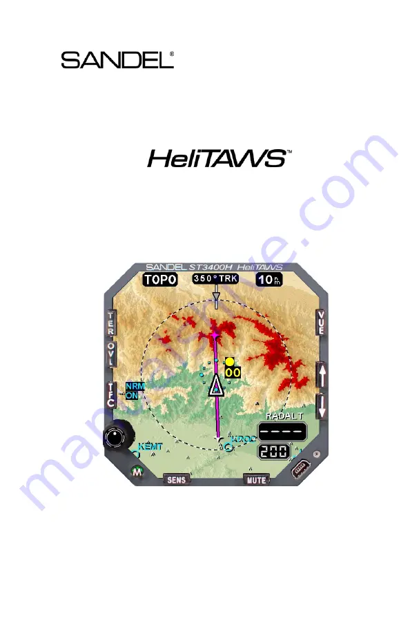
background image


ST3400H 


Helicopter  

Terrain Awareness  

Warning System 


Pilot’s Guide 


Revision B1 

Summary of Contents for ST3400H HeliTAWS

Page 1: ...ST3400H Helicopter Terrain Awareness Warning System Pilot s Guide Revision B1...

Page 2: ...82046 PG B1 ST3400H PILOT S GUIDE Page ii This page intentionally left blank...

Page 3: ...Other Features 3 3 4 SYSTEM OVERVIEW 4 1 4 1 Design Cruise Altitude 4 1 4 1 1 Sensitivity 4 1 4 2 Off Airport Landings 4 1 4 3 Alerts Warnings and Cautions 4 1 4 4 TAWS Inhibit 4 2 4 5 Display 4 2 4...

Page 4: ...Annunciation 6 3 6 4 Responding to an Alert 6 3 6 5 Alert Circle 6 4 6 5 1 Terrain 6 4 6 5 2 Obstacles 6 4 6 6 Obstacle Symbology 6 5 6 6 1 Obstacles in TOPO Display 6 5 6 6 2 Obstacles in REL Display...

Page 5: ...TEST 10 3 10 4 TCAS TEST 10 4 10 5 Traffic System Altitude Mode 10 5 10 6 Brightness 10 6 10 7 System Status 10 6 10 7 1 Equipment List 10 7 11 EXTERNAL SWITCH AND ANNUNCIATORS 11 1 12 ON SCREEN ANNUN...

Page 6: ...ine 5 16 Figure 6 1 CAUTION TERRAIN Annunciation 6 1 Figure 6 2 Terrain Alert Flying Toward Obstacle Level Flight 6 2 Figure 6 3 Terrain Alert Flying Toward Obstacle Descending Flight 6 2 Figure 6 4 W...

Page 7: ...82046 PG B1 ST3400H PILOT S GUIDE Page vii Figure 10 7 Dimmer Mode 10 6 Figure 10 8 System Status 10 6 Figure 12 1 On Screen Annunciation 12 1...

Page 8: ...82046 PG B1 ST3400H PILOT S GUIDE Page viii This page intentionally left blank...

Page 9: ...t No 750 651 China Patent No 1211639C Israel Patent Nos 135 174 153 460 and 155 983 All rights reserved No part of this manual may be reproduced stored or distributed without written permission of San...

Page 10: ...ion Regulations to have on board current charts appropriate to the flight The moving map on the ST3400H does not fulfill this requirement Current internal databases are not required but are recommende...

Page 11: ...o This manual uses terms which should be familiar to aviation minded readers such as Radar Altitude and Magnetic Heading Terms which are specific to the ST3400H will be placed in the glossary 1 8 Effe...

Page 12: ...navigation The Obstacle Database does not include power lines Low Sensitivity or Off Airport Modes must not be selected when operating under IMC conditions except as required when performing offshore...

Page 13: ...nd in any selected display mode Pilot selection of low sensitivity and off airport operational modes allows nuisance free protection in very demanding missions The terrain display features a new plan...

Page 14: ...rious advisories FLTA provides predictive look ahead warnings by comparing its internal terrain and obstacle database to position information provided by the GPS receiver The internal terrain and obst...

Page 15: ...istances up to 20nm An internal data recorder automatically records a minimum of the last twenty hours of flight data Oldest data is automatically overwritten with most recent data This data can be us...

Page 16: ...e altitude to prevent color flooding 4 2 Off Airport Landings In addition an Off Airport Mode is pilot selectable which operates at either Sensitivity Alerts are normally automatically suppressed duri...

Page 17: ...igned to only alert when the aircraft is outside normal flight envelopes in relation to terrain we recommend that all alerts should result in immediate and appropriate action by the pilot A Warning sh...

Page 18: ...can function as an optional primary or secondary Radar Altimeter indicator when interfaced to a compatible Radar Altimeter system Digital RADALT Radar Altitude and a MINS setting window are provided...

Page 19: ...by Jeppesen See Chapter 17 for Terms and Conditions regarding the use of the databases contained within the ST3400H 4 7 1 Coverage area of the database The internal database of the ST3400H includes te...

Page 20: ...unctional element 5 1 Control Overview The ST3400H physical layout consists of a display screen 9 backlit buttons one push pull rotary knob and one USB connector Terrain REL TOPO Reserved Traffic Mode...

Page 21: ...GUIDE Page 5 2 5 2 Display Overview The display is composed of underlying terrain with symbol and text overlays The display is geometrically referenced to the tip of the symbolic aircraft Figure 5 2...

Page 22: ...will light at night brightness level when power is applied and the display will be blank for approximately 25 seconds 5 4 Initial Bootup Display After approximately 25 seconds after initial power up...

Page 23: ...power up display is removed the operating screen will likely show sensors in the failed state until they become available Figure 5 4 Initial Display As soon as sensor availability is established the t...

Page 24: ...een 360 degree and 70 degree ARC views Figure 5 5 FULL and ARC Views This action only affects the screen display it has no affect on alerting The ARC view maximizes the display of the ground track ahe...

Page 25: ...shown in blue Other water is shown only by its elevation color coding 5 7 2 REL DETAILS On the Relative Altitude display only proximate terrain is shown Terrain with adequate terrain clearance is blac...

Page 26: ...REL Display Color Banding relative to aircraft altitude 5 9 Display Orientation The display orientation HDG TRK is selected automatically and is shown within a box at the top of the display When displ...

Page 27: ...e aircraft is going to be on its current ground track Figure 5 8 Display Orientation TRK is used above 35Kts ground speed HDG is used below 30Kts ground NOTE Traffic symbols are always referenced to t...

Page 28: ...the distance in nautical miles between the tip of the symbolic aircraft and the dashed range ring Switching between FULL and ARC view maintains the terrain cell size during range changes Figure 5 9 D...

Page 29: ...DE Page 5 10 5 11 Overlay The OVL button is reserved for a future feature Pressing this button when in the normal display mode not in the pilot menu will display the message NOT IMPLIMENTED Overlay Bu...

Page 30: ...The Heading Pointer shows the magnetic heading of the aircraft where it is pointed and can be used for identifying the crab angle In the following illustration the wind is coming from the right and th...

Page 31: ...to toggle the Sensitivity between NORM and LOW NORM has no screen annunciation LOW displays LOW SENS as shown in the figure SENS Button Low Sensitivity Mode Annunciator Figure 5 13 Alert Sensitivity S...

Page 32: ...ff Airport Mode HOLD the SENS button to toggle the OFF APT mode This annunciates OFF APT in Cyan SENS Button Off Airport Mode Annunciator Figure 5 14 Off Airport Mode Selection Note This function may...

Page 33: ...e mute function Figure 5 15 MUTE Button Highlighting Notes In the special case of a GPWS Altitude Loss After Take off alert DON T SINK pressing MUTE will disarm the alert completely until the next tak...

Page 34: ...B1 ST3400H PILOT S GUIDE Page 5 15 5 16 Brightness Figure 5 17 Brightness Pull the knob and turn to adjust the brightness The brightness is shown above the knob as a number from 0 100 100 is full bri...

Page 35: ...active flight plan segment is colored magenta and the balance of the flight plan segments are colored white NOTE Display of DME arcs Holding Patterns and Procedure Turns is not currently supported in...

Page 36: ...ted position is based on current aircraft location and the aircraft s ground speed The projected altitude is based on current aircraft altitude and the aircraft s vertical speed The aircraft s project...

Page 37: ...ning may be received without a Caution In some cases a terrain alert may be issued while flying toward an obstacle This will occur when terrain beneath the obstacle is within the terrain alerting buff...

Page 38: ...ay be other areas of conflict In Figure 6 1 note the alert is on a green cell and in Figure 6 4 the alert is on a yellow cell Both represent terrain below the aircraft This is occurring because the ai...

Page 39: ...terrain is subject to uncertainties and tolerances the terrain or obstacle threat may be anywhere inside the circle 6 5 2 Obstacles For obstacle alerts the size of the Alert Circle displayed on the ST...

Page 40: ...een the same symbol depicted at different sizes Coloring of obstacles is in accordance with the REL Color Chart in Figure 5 7 with the exception that there is only one RED color band i e red means abo...

Page 41: ...imity to the helicopter Note that obstacles far from the helicopter are shown very small for situational reference planning only These will drop out of view in REL mode Figure 6 7 Obstacles in TOPO Di...

Page 42: ...cles near the helicopter altitude where RED YEL GRN color coding is enforced The obstacles below the green altitude drop out of the display completely Figure 6 9 Obstacles in REL Display Figure 6 10 O...

Page 43: ...to the attention of Sandel Avionics for analysis Be aware that the TAWS INH function cancels all alerts FLTA and GPWS Altitude Callouts remains active and terrain is removed from the screen 6 8 Simul...

Page 44: ...er installed 7 1 Mode 1 Excessive Rate of Descent A SINK RATE Caution Alert is generated when the aircraft height above terrain is below 500 AGL and is accompanied by a high rate of descent If the des...

Page 45: ...GLIDESLOPE Caution Alert is generated if the aircraft descends below the glideslope when the aircraft is 400 AGL or lower while in the Normal Sensitivity mode 200 or lower while in the Low Sensitivit...

Page 46: ...ILOT S GUIDE Page 7 3 7 7 TAWS INH GPWS GPWS alerting can be inhibited with the TAWS INH function The TAWS INH function also cancels all FLTA alerts When TAWS INH is active Callouts remains active Fig...

Page 47: ...ver the MINS setting window is retained and may be used by the pilot as a reference number Radar altitude displays in 5 increments below 200 10 increments below 1000 and 20 increments below 2000 The k...

Page 48: ...e specific traffic system installed in the aircraft for a complete description of the capabilities When a traffic processor is not installed pressing the TFC button will display a NOT CONFIGURED advis...

Page 49: ...our aircraft are displayed ABV Above altitude display mode Target aircraft within 2 700 ft and 9 000 ft of your aircraft are displayed BLW Below altitude display mode Target aircraft within 9 000 ft a...

Page 50: ...s of closure or within 0 20 to 0 55nm and 600 to 800 ft of your aircraft No Bearing No Altitude Traffic Advisory TA with no bearing and no altitude information available No Bearing Traffic Advisory TA...

Page 51: ...aft altitude The down arrow indicates the target is descending at a vertical rate greater than 500 fpm 9 6 2 Traffic Absolute Altitude The traffic processor may have an option to change the display of...

Page 52: ...1 GS INHIBIT GS soft key controls GPWS Mode 5 glide slope alerts NORM or INH disabled When in INH the glide slope warning is disabled Note The Mode 5 alert is also automatically disabled when flying...

Page 53: ...een This feature is used for Abnormal failure of GPS FMS resulting in erroneous data A conventional flagged GPS FMS failure will automatically fail alerts and the terrain display To eliminate nuisance...

Page 54: ...y performs the following functions Tests external annunciator lamps if installed Tests on screen annunciation of CAUTION followed by WARNING Tests audio system with CAUTION followed by WARNING audio T...

Page 55: ...a TCAS TEST output discrete for BFG traffic systems Press the knob to perform the TCAS TEST Consult the Rotorcraft Flight Manual Supplement for the ST3400H installation for you aircraft and the traffi...

Page 56: ...ced to the ST3400H in your particular installation these altitude filtering modes may be controllable through this soft key Descriptions for these modes can be found in Chapter 6 TRAFFIC DISPLAY Consu...

Page 57: ...is the only mode that is currently supported by the ST3400H Dimmer Mode Figure 10 7 Dimmer Mode 10 7 System Status The System Status box contains a list of failed or inoperative equipment The UP DOWN...

Page 58: ...ADC Air Data Computer AP Autopilot engaged input inop TAWS INH Taws Inhibit input inop FMS GPS Flight Management System input GPS GPS Flight Management System input GEAR Landing Gear INOP ARINC 429 o...

Page 59: ...etc This will correspond with a flagged terrain display The supported external switch annunciators are MUTE illuminates whenever the MUTE is displayed on the ST3400H Pressing the external MUTE switch...

Page 60: ...on the Failed Equipment List NO HDG Loss of heading information or no heading system configured when GPS track is not available TAWS FAIL FLTA alerts and TOPO and REL displays are disabled due to lac...

Page 61: ...ly temperature Pull CB and report to maintenance OVER TEMP Over temperature Pull CB and report to maintenance 400 HZ FAILED 400 Hertz failed Aircraft inverter failure May affect HDG operation 400 HZ L...

Page 62: ...e TERR INH TERR INCOMPATIBLE Terrain database version compatibility failure Terrain data not usable FLTA not airworthy use TERR INH MAP TERR CONFLICT Map and terrain compatibility failure FLTA not air...

Page 63: ...display is shown with an indication of the cause of the error If the cause of the error is an erroneous CRC Cyclic Redundancy Check then the expected and calculated CRC is displayed If the cause of th...

Page 64: ...2 Flight Data The ST3400H has an internal recorder that automatically records a minimum of twenty hours of flight data Oldest data is automatically overwritten with most recent data This data can be...

Page 65: ...Collision Avoidance System TCAS Airborne Equipment TCAS 1 Software Certification RTCA DO 178B Level C Programmable Logic RTCA DO 254 Level C Environmental Category A2F1Z BBB UU2 XXXXXXZZAZ ZW WW M A3G...

Page 66: ...Closure Rate to Terrain EDGSD Excessive downward Glideslope Deviation EMS Emergency Medical Service ERD Excessive Rates of Descent FAA Federal Aviation Administration FITNL Flight Into Terrain Not in...

Page 67: ...VIS Night Vision NM Nautical Miles POST Power On Self Test RA Resolution Advisory RFMS Rotorcraft Flight Manual Supplement RTCA Radio Technical Commission on Aeronautics rtca org TA Traffic Advisory T...

Page 68: ...d others who must be thoroughly familiar with and competent in among other things the planning of flights and the computerized flight planning programs being used NavData does NOT contain all informat...

Page 69: ...CABLE 28 DAY PERIOD FOR WHICH THE NAVDATA IS PRODUCED AND IS EFFECTIVE IS THE ONLY WARRANTY EXPRESS OR IMPLIED ARISING BY LAW OR OTHERWISE MADE BY JEPPESEN REGARDING ITS NAVDATA JEPPESEN S SOLE OBLIGA...

Page 70: ...ppesen and its subcontractors from and against all claims and liabilities including claims by third parties and costs and expenses including attorneys fees incident thereto or incident to successfully...

Page 71: ...ot exclude or limit a warranty or liability implied by law this agreement shall be read and construed subject to such provisions of law EXPORT COMPLIANCE End user shall be responsible for its complian...

Reviews: