background image

SLIM

EN

Summary of Contents for SLIM Series

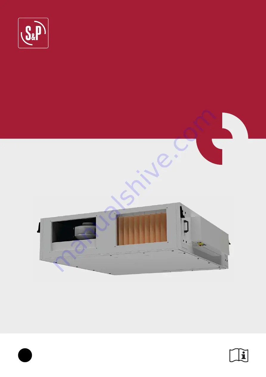
Page 1: ...SLIM EN...

Page 2: ......

Page 3: ...Connection with air duct 18 13 1 1 Schematic air duct connection example 19 13 1 2 Isolation dampers accessory 19 13 1 3 Flexible connections accessory 19 13 2 Connection with coil piping 20 14 ELECTR...

Page 4: ...50 24 1 Con gure a time program 50 24 2 De ne holidays 51 24 3 De ne intervals for recirculation 51 24 4 Time programming overview 51 25 FIRE MODE 52 26 SMOKE MODE 52 27 WATER HEATER FROST PROTECTION...

Page 5: ...f ciently resistant to withs tand the unit s weight and that of the accessories Do not open the access doors without rst switching off the electrical power supply with the main power switch pre sent o...

Page 6: ...t in accordance with the recommendations in our instructions de fects observed as a result of normal wear and tear incidents caused by negligence lack of monitoring or maintenance defects due to incor...

Page 7: ...ring elements can bear the weight of the device taking into account that it is a dynamic load To prevent the transmission of vibrations it is necessary that the installer use speci c isolation element...

Page 8: ...G H SL 800 1700 1659 1080 1130 380 400 420 200 220 85 110 110 SL 1200 1700 1659 1560 1610 380 500 520 250 270 155 250 110 SL 1600 1700 1659 1760 1810 420 600 620 300 320 155 250 110 SL 2000 2000 1953...

Page 9: ...9 1080 1130 380 400 420 200 220 85 110 110 SL 1200 1700 1659 1560 1610 380 500 520 250 270 155 250 110 SL 1600 1700 1659 1760 1810 420 600 620 300 320 155 250 110 SL 2000 2000 1953 1760 1810 500 600 6...

Page 10: ...P Q F E H B G IA C T R S DETAIL Z D d DETAIL Z d D Z AIR SENSE Z AIR SENSE Module A B C d D E F G H IA J K L SL 800 700 540 380 17 22 73 145 584 482 685 400 200 420 SL 1200 700 780 380 17 22 73 145 8...

Page 11: ...n the level of condensate grows over a set point If there is any problem related with the condensates drainage defective pump maximum level of condensates reached etc unit will display an alarm in the...

Page 12: ...pump SLIM R 9 DIMENSIONS AND FREE SPACE FOR MAINTENANCE 9 1 UNITS WITH NO EXTERNAL MODULE ASSEMBLED SLIM can be installed close to the wall as long as no external module has been assembled Maintenanc...

Page 13: ...and motors C hydraulic connections external DX and water modules C electrical connections external DI modules SLIM 800 600 380 650 200 SLIM 1200 800 380 900 200 SLIM 1600 900 420 1000 200 SLIM 2000 95...

Page 14: ...eci c hinged panel for lter replacement b Push from the xation pieces to loose the ltration box c Remove the ltration box d Remove the lter from the ltration box rst step is to push from the pie ces t...

Page 15: ...f an electrical preheater 11 2 1 External module electrical post heaters ELECTRIC POST HEATER Type Outdoor Air ODA Indoor Air ETA Supply Air SUP1 before the coil Supply power kW Absorved current A Air...

Page 16: ...800 63 2 96 0 6 32 72 0 6 1 2 5407037900 3WV DN15 KVS1 PROP 24V SL DFR 1200 3 10 8 10 C 90 20 C 50 11 2 C 19 3 50 40 7 17 28 4 6 5 1200 61 2 78 0 62 12 50 1 1 2 5407038000 3WV DN15 KVS1 6 PROP 24V 70...

Page 17: ...ooling power kW kg h kPa Supply Air SUP2 after the coil Heating power kW kg h kPa Supply Air SUP2 after the coil Flow rate m3 h Pressure drop Pa Speed m s SL DX 800 4 9 7 35 C 40 26 C 50 28 C 60 4 48...

Page 18: ...l working condi tions Temperature and ambient relative humidity and evaporation temperature considered DX coil pressure drop as well as internal coil volume are compatibles with the KIT DX VALVE not s...

Page 19: ...during the night or during periods of prolonged unit stoppage When talking about the indoor air connections If the ductwork is expected to pass through cold areas it must be isolated Model Isolation...

Page 20: ...f lling valve to keep the appropriate water level Pressure switch to detect the lack of water pressure Shut off valves must be installed at each connection on the water line to allow the unit to be is...

Page 21: ...73 D14 74 D15 75 D16 76 D11 71 D17 77 D18 78 Disp B 50 A 51 N 52 E 53 P 1 P1 RxTx TCP IP P B 111 11 110 10 109 9 108 8 107 7 106 6 105 5 104 4 103 3 102 2 101 1 100 C 1 G 2 GO 3 4 C 10 G DO 11 DO1 12...

Page 22: ...BLOCKS TRANSFORMER RELAYS DISTRIBUTOR Notes Terminal blocks Terminals in which the installer has to carry out with the connections see section 14 4 External components connection drawings examples Tr...

Page 23: ...23 14 3 FACTORY WIRING 14 3 1 SLIM 800 SLIM 1200 without preheater CONTROLLER E28 MDB F CONTROLLER E15 CONTROLLER 1 E28 SD EAF SAF CP CONTROLLER 2 E15 F...

Page 24: ...24 14 3 2 SLIM 1600 SLIM 2000 without preheater CONTROLLER E28 MDB F CONTROLLER E15 CONTROLLER 1 E28 SD EAF SAF CP CONTROLLER 2 E15 F...

Page 25: ...25 14 3 3 SLIM 800 SLIM 1200 with preheater CONTROLLER E28 MDB F CONTROLLER E15 CONTROLLER 1 E28 SD EAF SAF CP CONTROLLER 2 E15 1 ELECTRIC PREHEATER 2 2 2 1 2 2 2 1 1 ELECTRIC PREHEATER...

Page 26: ...26 14 3 4 SLIM 1600 SLIM 2000 with preheater CONTROLLER E28 MDB F CONTROLLER E15 CONTROLLER 1 E28 SD EAF SAF CP CONTROLLER 2 E15 F 1 ELECTRIC PREHEATER 2 1 2 2 ELECTRIC PREHEATER 2 2 2 1 1...

Page 27: ...HHG 6PRNH DODUP 3 0 3RVW KHDWHU FRQWURO 3 0 3UH KHDWHU FRQWURO LUH ODUP 2YHUKHDWHG OHFWULF 35 KHDWHU JURXS GHIURVW QHUJ PHDVXUHPHQW 6 SUHVVXUH WUDQVPLWWHU IRU PHDVXULQJ RZ SUHVVXUH WUDQVPLWWHU IRU PHD...

Page 28: ...essure transmitter for measuring flow 32 C2 GND 0 10V AI2 2 EAF pressure EAF pressure transmitter for measuring flow 33 24V GND 0 10V UI3 1 VAV control External probe connection for VAV control CO2 HR...

Page 29: ...0 R SLIM 2000 L 5416744200 IJK 315 5416762900 LF 230 S SLIM 2000 R 14 4 2 CAV wiring diagram See section 11 3 Electrical preheaters delivered as accessories for detailed information regarding CAV mode...

Page 30: ...G QG QG 5HPRWH 21 2 WHUQDO VZLWFK RQWDFW FORVHG 8QLW UXQQLQJ 9 H WHUQDO VLJQDO 6 0 HOHFWULFDO FDELQHW 9 QG 14 4 4 COP wiring diagram See section 11 3 Electrical preheaters delivered as accessories for...

Page 31: ...unit and connect the supply as shown below 21752 32 5 1 3 6LQJOH SKDVH 9DF 6XSSO YROWDJH 1 3 SKDVH 9DF 6XSSO YROWDJH 3 0B QG QG QG QG QG QG QG 9 9 QG 9 6XSSO LU 7HPSHUDWXUH 6HQVRU 2YHUKHDWHG OHFWULF...

Page 32: ...thermostat that must be connected to the SLIM electrical cabinet The external module is delivered with a terminal box to easy the connection Connect the terminals from the CONTROL TERMINAL BOX water c...

Page 33: ...The system is designed to perform heating or cooling independently but not at the same time There is not possibility to dehumify either Connect the terminals from the CONTROL TERMINAL BOXES water coil...

Page 34: ...nufacturer of the DX group includes the gas valve the temperature probes and the electronic board that perform the operation management in these cases our SLIM units will act as slave units and it wil...

Page 35: ...QG QG QG QG QG QG QG 6 0 HOHFWULFDO FDELQHW JURXS GHIURVW 5HYHUVLEOH FRQWURO KHDWHU FRROHU LJLWDO LQSXW RQWDFW FORVHG 2XWGRRU XQLW LQ GHIURVW PRGH HDWLQJ RROLQJ GHPDQG 7R EH VHQW WR WKH JURXS LI UHTX...

Page 36: ...36 15 1 STANDARD UNIT 3 7H 7L 7 7U 3 3 0 0 3 3 15 2 SLIM PH WITH ELECTRICAL PREHEATER 3 7H 7L 7 7U 3 3 0 0 3 3 3 15 3 STANDARD UNIT ELECTRICAL BATTERY POST HEATING 3 7H 7L 7 7U 3 3 0 0 3 3...

Page 37: ...T HOT WATER COIL POST HEATING 3 7H 7L 7 7U 3 3 0 0 3 3 15 5 STANDARD UNIT REVERSIBLE WATER COIL POST TREATMENT 3 7H 7L 7 7U 3 3 0 0 3 3 5 15 6 STANDARD UNIT CHILLED WATER COIL POST REFRIGERATION 3 7H...

Page 38: ...asing speed when pressure rise Time programming Weekly timer holiday periods Remote Normal Speed and Remote Extra Speed Via external potential free contacts Remote ON OFF Contact to connect an externa...

Page 39: ...P 21 0 C 1500 m3 h 1500 m3 h User 12 32 28 09 21 Run mode On Control mode Supply Air Control Menu User 17 2 SIMPLIFIED MENUS ACCESSES There are 3 access levels to the controller User level no passwor...

Page 40: ...1371 m h 50 Supply Air Fan Actual Air ow Control signal 3 1371 m h 50 Extract Air Fan Actual Air ow Control signal Check alarm list Menu Alarms User No active alarms S P 21 0 C 1500 m3 h 1500 m3 h Use...

Page 41: ...t time 5 min Select language English Version XX XX XX Time settings change date Menu Service Timer Menu Service Date Time Time Schedule Date Time Service Date Day of week Time Automatic switch between...

Page 42: ...xternal 0 10V sensor accessory COP Operation at constant pressure by means of an external accesory TDP S After a change in the selected operation mode the fans stop and re start in the new selected mo...

Page 43: ...nt manually selected Auto Selection of the set point is done according to the time programming Advanced level Independent SAF and EAF ow control SAF and EAF are controlled each one by its respec ve pr...

Page 44: ...umping and dumping constantly Increase P Band Reduce I time Slow regulation Airflow set point is not achieved While the fans do not reach their maximum speed the increase in its speed is low Reduce P...

Page 45: ...AV mode automatically con gures the FAN MENU screen adapting it to the VAV mode Stop the unit stop Manual Manually selection of air ow setpoint by percentage If Manual is selected unit won t follow th...

Page 46: ...o choose among two COP control modes Pressure control in supply fan SAF while extract fan EAF works as slave SAF is controlled by the pressure transmi tter signal and EAF follows SAF by a balance fact...

Page 47: ...P wiring diagram Stop Stop de unit Reduced pressure Normal pressure Manually selection of the pressure Auto Selection of set point is done according to time programming see section 24 TIME PROGRAMMING...

Page 48: ...ver you can manually change the set point from the main screen 3 C 0HQX 6HUYLFH 6HWWLQJV 6HUYLFH 23 9 9 9 9HQWLODWLRQ PRGH WUDFWLRQ LU FRQWURO RQVWDQW VXSSO DLU 7 RPSHQVDWHG VXSSO DLU 6XPPHU ZLQWHU FR...

Page 49: ...ivation to occur are as follows ALL the conditions must be satis ed Start conditions Less than 4 days have elapsed since the last start of the installation The outdoor temperature during the previous...

Page 50: ...de these intervals the fans are stopped The installer can de ne up to 4 ope ration intervals per day in each speed Find the procedure to set the time schedule below Particularities of the mode VAV Aut...

Page 51: ...st follow these steps 24 3 DEFINE INTERVALS FOR RECIRCULATION In case a mixing damper is installed it is possible to de ne intervals for recirculation 24 4 TIME PROGRAMMING OVERVIEW Finally the overvi...

Page 52: ...n Continuous run with the supply air fan being stopped while the extract air fan will a follow the normal set point if the unit was running at normal speed or reduced speed before the activation of th...

Page 53: ...functionality prevents freezing of the condensates existing inside the heat exchanger on the side of expulsion of air to the outside In order to protect the heat exchanger the SLIM controller implemen...

Page 54: ...0039700 SL DF 1600 5 R 5800040500 SL DX 1600 4 R L 5800041200 SL DI 1600 7 5 T L 5800038800 SL DC 1600 2 L 5800042000 SL DFR 1600 3 L 5800039600 SL DF 1600 5 L 5800040400 SL DX 1600 4 L SLIM 2000 R 58...

Page 55: ...and a nut and they are supplied assembled when purchasing an external module like in the following picture Screw the cap screws until the nut touches the unit 2 Once the cap screws have been screwed o...

Page 56: ...WKH KROHV ZKHUH WKH FDS VFUHZV WKDW KDYH EHHQ DVVHPEOHG WR WKH XQLW LQ VWHS VKRXOG HQWHU 3 Approach the external module to the main unit until the cap screws are into the closing system When approachi...

Page 57: ...be a rub ber seal bettween the unit and the external module we can conclude that tightness is properly ensured 29 2 CONFIGURATION OF EXTERNAL MODULES OF REFRIGERATION HEATING BATTERIES Once the corre...

Page 58: ...vide preheating electric batteries located in the outside air intake of the heat recovery unit The preheater increases the temperature of the outdoor air avoiding the continued ac tivation of heat exc...

Page 59: ...s Fan and condensate tray will be visible Outdoor duct connections Indoor duct connections DQ RQGHQVDWH WUD c Turn the condensate tray over itself d Remove the speci c panel for electrical preheater l...

Page 60: ...tray back in the original position step c of this procedure and remove the lter through the bottom see section 10 1 Removing the lter through the bottom Taking a view across the ltering section it is...

Page 61: ...19 1 Commissioning should now be re set up together with en suring that the additional parameters Language K Constant heater type etc are correct For further details check section 19 INSTALLER LEVEL...

Page 62: ...eeds available 9600 default 19200 38400 or 76800 Modbus communication takes place using 1 stop bit it is pos sible to activate 2 bits stop Parity could be modi ed as well The modbus comunication must...

Page 63: ...TO BMS BACNET COMMUNICATION PROTOCOL 32 2 1 BACnet MS TP on port 1 RS485 Controller number 1 see section 14 2 1 External electrical box composition has a RS485 communication port P2 that can be dedi...

Page 64: ...oller number 1 see section 14 2 1 External electrical box composi tion is equipped with one TCP IP communication port RJ45 connector 0HQX 6HUYLFH 20 6HWWLQJV 6HUYLFH 20 6HWWLQJV 6HUYLFH JQG 8 8 JQG 8...

Page 65: ...4 Auto COP parameters Setpoint full speed supply air fan pressure HR R W 24 AV 30024 500 Pa 5000 SAF Manual normal pressure Pa Setpoint reduced speed supply air fan pressure HR R W 25 AV 30025 300 Pa...

Page 66: ...output IR R 119 AV 40119 Control signal heating Y1 0 10 V Cooling control signal output IR R 121 AV 40121 Control signal cooling Y3 0 10V BY PASS By pass control By pass running mode HR R W 379 NA 0 O...

Page 67: ...ISR R 131 BV 20131 0 0 1 Extraction Air Filter needs replacement Alarm Acknowledgement Acknowledgement of individual alarms HR R W 400 NA To acknowledge an alarm set this signal its alarm number 1 Mal...

Page 68: ...ull up gently until the battery exits from its holder Replace the battery with a new Warning be sure to respect the polarity when inserting the battery 33 2 REPLACEMENT OF FILTERS The SLIM control inc...

Page 69: ...d Replace filter Insufficient rotation speed Check power supply voltage Exchanger blocked Clean the exchanger Reduction in performance after a period of acceptable operation Leaks in the circuit befor...

Page 70: ...0 TRANSMISOR PRESION 0 1000 PA Pressure transmitter Same pressure transmitters are used on all 4 sizes 800 1200 1600 2000 1 R153667114 PRESSURE SWITCH Pressure switch filter clogging Same pressure swi...

Page 71: ...nit may be re started remotely C Electric heating is overheated Electric heater thermal protectors activated A Frost risk Water heater frost protection function is overriding the control of water heat...

Page 72: ...S P SISTEMAS DE VENTILACI N S L U C Llevant 4 Pol gono Industrial Llevant 08150 Parets del Vall s Barcelona Espa a Tel 34 93 571 93 00 www solerpalau com Ref 9023095100...

Reviews: