background image

Part No.     SKSM0702      C5KEV

JULY 2004

Colour Television
Service Manual

Model CE21CM1F-C

Service Ref. No. CE21CM1F-C-00

PRODUCT CODE:  111360804 

ORIGINAL VERSION: Chassis No. EB7-B

Give complete "SERVICE REF. NO." for parts
order or servicing, it is shown on the rating sheet
on the cabinet back of the TV set.

Note
This TV receiver will not work properly in foreign
countries where the television transmission 
system and power source differ from the design
specifications. Refer to the specifications for the
design specifications

CE

21CM1F

-C

Contents
Safety precautions/Specifications  ..................................................................................................................2
Block diagrams ..............................................................................................................................................3
Cabinet Disassembly ......................................................................................................................................4
Adjustment and Repair Procedures............................................................................................................5~9
CPU Functions ..............................................................................................................................................................................10~11
Component Locations ............................................................................................................................12~13
IC Block Diagrams ..................................................................................................................................14~18
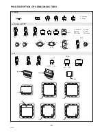
Pin description of semiconductors ................................................................................................................19
Part Description and reading of schematic diagram ....................................................................................20
Cabinet Parts List/TV Stand parts list ..........................................................................................................21
Electric Parts List ....................................................................................................................................22~26

Please use Schematic Diagram SKP20446 with
this Service Manual.

Summary of Contents for CE21CM1F-C

Page 1: ...e television transmission system and power source differ from the design specifications Refer to the specifications for the design specifications CE21CM1F C Contents Safety precautions Specifications 2 Block diagrams 3 Cabinet Disassembly 4 Adjustment and Repair Procedures 5 9 CPU Functions 10 11 Component Locations 12 13 IC Block Diagrams 14 18 Pin description of semiconductors 19 Part Descriptio...

Page 2: ...ent designated by mark No deviations from resistance wattage or voltage ratings may be made for replacement items designated by mark 1 An isolation transformer should be connected in the power line between the receiver and the AC line when a service is performed on the primary of the converter transformer of the set 2 Comply with all caution and safety related notes provided on the cabinet back in...

Page 3: ...0 IC1201 AV VIDEO SW LA7954 IC1401 RGB SW TC4053BF BLK R G B 45 18 17 16 15 34 33 54 11 21 20 8 1 19 MUTE IC801 CPU IC3451 NICAM STEREO RC IN A1901 RC RECEIVER KEY IN KEY SW SDA SCL SDA SCL IC803 MEMORY PROTECT POWER D641 9V IC642 D647 5V 1 27V IC643 Q661 Q651 Q682 Q685 25V 145V Q641 Q686 D615 13 14 11 18 15 5 3 2 8 Q611 SW901 D603 D606 AC C607 Q613 Reg C IN C IN Y IN Video Y IN Video Y Out Video ...

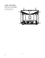
Page 4: ...CABINET BACK DISASSEMBLY 1 Remove 6 screws A for 21 2 Pull out the cabinet back 4 C5KEV CABINET DISASSEMBLY A A A A A A AV1 AV ...

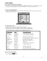
Page 5: ...lable option items and default setting mode Exit from the Service Mode Press the RECALL button Option Mode Mode Description Note ON TIMER ON or OFF On timer available default ON SORT MODE SORTING or Tuning mode default SORTING TUNING P P ON or OFF Plug Play mode default ON WEL TEXT ON or OFF Display message when first set up default ON COMB FILTER OFF or ON For factory use default OFF BBE ON or OF...

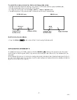
Page 6: ... P VSC P Vertical S Correction Adjustment 5 P V A P Vertical Size Adjustment 6 P H S P Horizontal Size Adjustment 7 P E P P Pin Cushion Adjustment 8 P E T P Trapezoid Distortion Adjustment 11 P ECT P Top Corner Correction Adjustment 12 P ECB P Bottom Corner Correction Adjustment 13 P HPA P Parallelogram Distortion Adjustment 14 P H B P Horizontal Bow 15 P VPH P Vertical Phase Adjustment 4 3 Vertic...

Page 7: ...NITIALISATION OF MEMORY IC To initialise the memory IC IC803 press and hold the NORMAL button on the remote control then press the P button on the front panel of the TV set and then turn the Mains switch Off and On The initialisation is now completed When initialised the memory IC and all of the setting data option data and service adjustment data stored in the IC are reset to the default value It...

Page 8: ...DJUSTMENT 1 Receive black white pattern 2 Enter to the service mode and select mode REGU LAR and select item no 2 REGULAR 2 CUT The horizontal line will appear on the screen 3 Set the SCREEN VR for one colour to be just visible 4 Using the numeric buttons shown set each colour to minimum by decreasing to the point where any further decrease resets the adjustment to maximum value BIAS ADJUSTMENT 5 ...

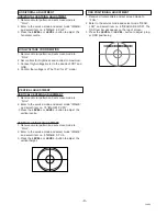
Page 9: ... FULL 2 Enter to the service mode and select mode IMAGE and select item no 15 IMAGE1 P VPH 3 Press the LEVEL or LEVEL button to adjust the vertical centre VERTICAL HEIGHT ADJUSTMENT 1 Receive circular pattern and set screen mode to FULL 2 Enter to the service mode and select mode IMAGE and select item no 5 IMAGE 5 P V A 3 Press the LEVEL or LEVEL button to adjust the vertical height 1 Receive circ...

Page 10: ...tput OUT 19 SDA SDA IN OUT 20 SCL SCL OUT 21 VDD Power 22 Not used 23 Not used 24 Not used 25 AVDD3 Analogue VDD of PLL 26 TEST0 Test 27 MCFM Test 28 29 TXCF Analogue pin for Teletext slicerline PLL 30 31 AVDD2 Analogue power supply 32 Not used 33 Video input H F IN 34 Video input L F IN 35 Not used 36 Not used 37 Not used 38 PXFM Analogue pin for the Display Pixel Frequency Multiplier 39 VDDA 40 ...

Page 11: ...Function Name Function IN OUT 51 OSC Clock oscillator IN 52 AGC Auto gain control IN 53 Not Used 54 POWER RL Power relay On Off control OUT 55 8PIN SC2 AV2 Scart function input IN 56 8PIN SC1 AV1 Scart function input IN ...

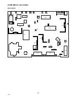
Page 12: ...07 R602 T611 TP B Q432 IC501 VR641 IC643 IC642 IC641 IC803 IC801 IC3451 IC001 T131 A101 KCPA TP A IC1201 IC1401 SW501 KP IC201 X132 X131 K1002 K1001 SW1901 SW1902 SW1903 SW1904 A1901A SW691 C601 L601 PS601 F601 RL691 SW1905 SW1906 K1101 K1921 MAIN BOARD ...

Page 13: ... DIGITAL SUPPLY DIGITAL SELECT I2C BUS AUDIO INTERFACE TIMING DETECT DAC NICAM DEMODULA TION FM AM DEMODULA TION IDENTIFICA TION I2C BUS INTERFACE INPUT SWITCH AGC ADC SIF1 SIF2 4 2 1 12 59 5 60 61 10 11 13 19 SDI1 SDI2 SDO1 SDO2 SCK WS V DDD1 V DDD2 V SSD1 V SSD2 CREST TEST1 TEST2 SYSCLK XTALO XTALI SDA SCL ADDR2 ADDR1 P2 P1 18 17 16 14 15 7 56 6 41 8 20 22 49 50 52 53 MOL MOR AUXOL AUXOR VSSA4 V...

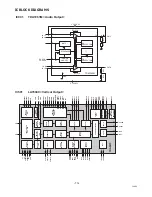
Page 14: ...BLACK det YS YCbCr cb2 B in cb3 in cr3 in Y3 CVBS3 in Y CVBS1 in c in IF DET OUT DAC 1 DAC 2 DAC 3 cr out cb out Y MON out cbr2 R in Y2 CVBS2 G Syncout H V Sync AFC1 HAFC gain V freq wide blanking H drive AFC2 PalaG Baw YUVSwitch Y C YCbCr2 YCbCr3 V EW EW corner T B Size Trapeze Parabola V Size VCentre VLinear V S I2C Bus IF Y2 Proc Black stretch DC Resistor WPL A C WPS UV Proc BBTINT Colour Contr...

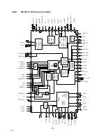
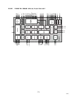
Page 15: ...ENTIFICA TION I2C BUS INTERFACE INPUT SWITCH AGC ADC SIF1 SIF2 4 2 1 12 59 5 60 61 10 11 13 19 SDI1 SDI2 SDO1 SDO2 SCK WS V DDD1 V DDD2 V SSD1 V SSD2 CREST TEST1 TEST2 SYSCLK XTALO XTALI SDA SCL ADDR2 ADDR1 P2 P1 18 17 16 14 15 7 56 6 41 8 20 22 49 50 52 53 MOL MOR AUXOL AUXOR VSSA4 Vref3 VDDA3 Vref n Vref n Vref2 V SSG V SSA2 V DDA2 PCAPL PCAPR CAPR2 CAPR1 CAPL1 CAPL2 LOL LOR SCOL2 SCOR2 SCOL1 SC...

Page 16: ...K A K A C B E C B E C B E 1 2 3 4 5 6 Index 1 2 N Index Index 1 2 N 2 1 3 IN OUT GND 2 1 4 2 1 3 Index 1 N Index 1 N Index 1 N Index 1 N Index 1 N Index 1 N 2 1 3 1 2 3 2 1 3 RESET GND Vdd 5 3 D G S D G S K Cathode A Anode C Collector B Base E Emitter D Drain G Gate S Source Diode Transistor FET IC E1 C2 E2 C1 B2 B1 Index Diode Transistor FET IC FET ...

Page 17: ...0 25 G 2 D 0 5 J 5 S 0 3 K 10 A 0 2 L 15 M 20 Coil Reading Capacitor Reading Example 1 2 D J 10K B Example 6 W K 8 2 Example 1 2 C K 1M Resistor Reading Characteristic Z Carbon fuse B Non burnable Resistance value Tolerance see below table Material see below table Rated wattage W K indicates in KΩ M indicate in MΩ Note Resistor which is indicated with resistance value only are 1 6W carbon resistor...

Page 18: ... G F7KC 5 610 297 9213 DEC IND C5WA 6 610 297 9190 BUTTON UNITED C5WA 7 610 253 2449 AC CORD HOLDER U D4VA 8 645 043 5058 BADGE SANYO 53 5X12L53 3 ACCESSORIES 9 645 052 2697 ASSY REMOCON JXMTA 645 027 6927 BATTERY 665 000 1916 INST MANUAL C5KE 1 665 000 1923 INST MANUAL C5KE 2 Item Part No Description Note Parts order must contain Service Ref No Part No and descriptions 3 5 8 8 4 2 6 1 ...

Page 19: ...9 9218 GRM188F51H103ZA01D PT115 C109 403 149 9218 GRM188F51H103ZA01D PT115 C110 403 149 9218 GRM188F51H103ZA01D PT115 C113 403 149 9218 GRM188F51H103ZA01D PT115 C120 403 248 1618 16 YK 47 M TA 0511 C1202 403 248 1618 16 YK 47 M TA 0511 C1203 403 149 9218 GRM188F51H103ZA01D PT115 C1204 403 233 0817 ELECT 10U M 50V C1205 403 233 0817 ELECT 10U M 50V C121 403 215 2211 GRM188R71H103KA01D PT115 C1212 4...

Page 20: ...1L PT297 C3452 403 314 5915 GRM21BR71C474KA01L PT297 C3453 403 157 2911 GRM1885C1H470JZ01D PT115 C3454 403 164 0214 GRM188F51E104ZA01D PT115 C3456 403 164 0214 GRM188F51E104ZA01D PT115 C3458 403 157 2911 GRM1885C1H470JZ01D PT115 C3459 403 248 1618 16 YK 47 M TA 0511 C3461 403 248 1410 ELECT 1U M 50V C3467 403 207 0317 GRM21BF51C105ZA01L PT297 C3476 403 314 5915 GRM21BR71C474KA01L PT297 C3477 403 2...

Page 21: ... TE 17 D645 407 099 5521 ZENER DIODE MTZJ T72 6 2C D646 407 149 0817 DIODE 1SS355 TE 17 D647 407 149 0817 DIODE 1SS355 TE 17 D663 407 063 8329 Z DIODE MTZJ T72 11C D666 407 063 8923 ZENER DIODE MTZJ T72 5 6C D683 407 149 0817 DIODE 1SS355 TE 17 D685 407 099 5620 ZENER DIODE MTZJ T72 6 8A D826 407 099 4821 Z DIODE MTZJ T72 4 3B INTEGRATED CIRCUIT IC001 409 301 4906 IC TDA7263M IC001 1 610 251 4186 ...

Page 22: ...K JA 1 16W R1042 401 024 6730 CARBON 100 JA 1 6W 52MM R1043 401 105 5311 MT GLAZE 4 7K JA 1 16W R1201 401 105 3218 MT GLAZE 270 JA 1 16W R1203 401 105 3218 MT GLAZE 270 JA 1 16W R1207 401 027 6638 CARBON 75 JA 1 6W 52MM R1215 401 105 0415 MT GLAZE 100 JA 1 16W R1217 401 105 5212 MT GLAZE 470 JA 1 16W R1226 401 105 0514 MT GLAZE 1K JA 1 16W R1227 401 105 3218 MT GLAZE 270 JA 1 16W R123 401 016 9811...

Page 23: ... 18 JA 2W R628 401 067 8204 OXIDE MT 39 JA 2W R631 402 000 8602 SOLID 5 6M KA 1 2W 52AMMO R632 402 000 8602 SOLID 5 6M KA 1 2W 52AMMO R636 401 024 7440 CARBON 10K JA 1 6W 52MM R637 402 067 8904 WIRE WOUND 3 9 KA 5W R641 401 105 5311 MT GLAZE 4 7K JA 1 16W R642 401 012 8155 CARBON 100K JA 1 4W 52MM R643 401 006 8114 CARBON 1 2 JA 1 2W R644 401 065 9609 OXIDE MT 18 JA 2W R645 401 014 5251 CARBON 15K...

Page 24: ... 105 7919 MT GLAZE 0 000 ZA 1 16W J617 401 105 7919 MT GLAZE 0 000 ZA 1 16W J622 401 105 7919 MT GLAZE 0 000 ZA 1 16W J631 401 105 7919 MT GLAZE 0 000 ZA 1 16W J691 401 105 7919 MT GLAZE 0 000 ZA 1 16W J820 401 105 7919 MT GLAZE 0 000 ZA 1 16W J821 401 105 7919 MT GLAZE 0 000 ZA 1 16W J822 401 105 7919 MT GLAZE 0 000 ZA 1 16W J827 401 105 7919 MT GLAZE 0 000 ZA 1 16W J828 401 105 7919 MT GLAZE 0 0...

Page 25: ...7D1 645 008 4058 TERMINAL PLUG K7M 645 008 4058 TERMINAL PLUG K7P 645 008 7288 HOUSING PLUG 5P K7Q 645 008 7264 HOUSING PLUG 3P K701 645 031 7699 CRT SKT HPS 014103 OUT OF CIRCUIT 013C5KZV COIL L901 645 034 1267 DEGAUSS COIL 21 42T 425 PICTURE TUBE Q901 414 011 4306 CRT A51EFS83X191 MISCELLANEOUS SP901 652 000 0663 SPEAKER 8 OHM 3 WATT 5 9 SP902 652 000 0663 SPEAKER 8 OHM 3 WATT 5 9 W901 645 012 7...

Page 26: ... 26 C5KEV ...

Page 27: ... 27 C5KEV ...

Page 28: ... 28 Sanyo Industries UK Ltd Printed in UK ...

Reviews: