

SERVICE MANUAL Colour Television
Specifications
Power Source
. . . . . . . .AC127-240V, 50/60Hz.
Colour System
. . . . . . . .PAL, NTSC4.43, NTSC, PAL 60Hz
Television System
. . . . .B/G
Channel Coverage
. . . . .VHF: E2-E12, R1-R12, K1-K9, J1-J12, A2-A13
UHF: 21-69, A14-A69, J13-J62
CATV: S1-S41, X, Y, Z, Z+1, Z+2
Video IF
. . . . . . . . . . . . . .38.0 MHz
Aerial Input Impedance
. 75
Ω
Ext. Terminals
Video inputs: Phono jack
2 (1.0Vp-p, impedance 75
Ω
)
DVD Input: Component Video Jack-Y
1 (1.0Vp-p, impedance 75
Ω
)
Component Video Jack CB/CR
1 (0.7Vp-p, impedance 75
Ω
)
Audio inputs: Phono jack (L/R)
2 (436mVrms, impedance more than 40K
Ω
)
Video monitor output: Phono jack
1 (1.0Vp-p, 75
Ω
)
Audio monitor outputs: Phono jack(L/R)
1(436mVrms, Impedance less than
600
Ω
)
Speaker
. . . . . . . . . . . . . . 5 cm
9 cm
2 pcs.
Sound Output (RMS)
. . . 5W + 5W
Dimensions
. . . . . . . . . . . 580 (W)
465 (H)
326 (D)mm
Weight
. . . . . . . . . . . . . . . approx. 19.7 Kg
Specifications subject to change without notice
Original Version
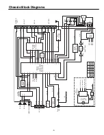
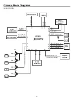
Chassis Series: FC8-A
BE4B
FILE NO.
Model No. CT21KS2
Service Ref. No. CT21KS2-00
(Thailand)
Give complete “SERVICE REF. NO.” for parts
order or servicing. It is shown on the rating plate
at the cabinet back of the unit.
This T.V. receiver will not work properly in
foreign countries where the television
transmission system and power source dif-
fer from the design specifications. Refer to
the specification table.
Product Code: 113016101
REFERENCE NO.
SM
3010349
1
2
3
4
5
6
7
8
9
0
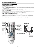
TV/AV
TIMER
x
-/--
SWAP
CH SCAN
MENU
BASS
SOUND S. SYS
SURROUND
PICTURE
CH
CH
A B
.
P
P
JXPSC
MENU
TV/AV
POWER
CH
- +
SM_21-BE4B (FC8-A) IDN 6/24/08 10:53 AM Page 1