background image

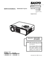
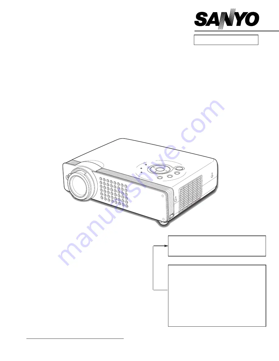
Multimedia Projector

SERVICE MANUAL  

PRODUCT CODE 
PLC-XU50                  PLC-XU55              
1 122 213 00

(MW3A)

1 122 211 00

(MT3A)

1 122 214 00

(PW3A)

1 122 212 00

(PT3A)

1 122 214 02

(PW3C)

1 122 212 02

(PT3C)

Original Version

REFERENCE NO.

SM

5110516-00

FILE NO.

Model No. PLC-XU50

PLC-XU55

U.S.A., Canada,
Europe, Asia, Africa
U.K.

Chassis No. MW3-XU5000

MT3-XU5500

NOTE:

Match the Chassis No. on the unit’s

back cover with the Chassis No. in the
Service Manual.

If the Original Version Service
Manual Chassis No. does not match
the unit’s

, additional Service

Literature is required. You must refer to
“Notices” to the Original Service
Manual prior to servicing the unit.

Summary of Contents for PLC-XU50

Page 1: ...110516 00 FILE NO Model No PLC XU50 PLC XU55 U S A Canada Europe Asia Africa U K Chassis No MW3 XU5000 MT3 XU5500 NOTE Match the Chassis No on the unit s back cover with the Chassis No in the Service Manual If the Original Version Service Manual Chassis No does not match the unit s additional Service Literature is required You must refer to Notices to the Original Service Manual prior to servicing...

Page 2: ..._________________34 Chassis over view ____________________________________________34 Inputs video signal processing stage____________________________35 LCD panel driving stage ______________________________________36 Audio signal processing circuit __________________________________37 System controls ______________________________________________38 Power supply protection circuit _________________...

Page 3: ...stray parts or tools have been left inside Before returning any projector to the customer the service personnel must be sure it is completely safe to operate without danger of electric shock SERVICE PERSONNEL WARNING Eye damage may result from directly viewing the light produced by the Lamp used in this equipment Always turn off Lamp before opening cover The Ultraviolet radiation eye protection re...

Page 4: ...jection Lens Throw Distance Projection Lamp Video Input Jacks RCA Type x 2 Audio Input Jacks DVI I Terminal Digital Analog HDCP compatible Mini Jack stereo x 1 Mini DIN 8 pin x 1 Mini Jack stereo x 1 variable with volume 1 0 W RMS Computer Input 1 Terminal Computer Component Audio Input Jack Service Port Connector Audio Output Jack Internal Audio Amp 0 to 11 8 Feet Adjustment Power Source AA UM3 o...

Page 5: ... like a screwdriver into a hole on the cabi net bottom 2 Press the reset button on the thermal switch with the screw driver CAUTION Before press the reset button make sure that the AC cord must be disconnected from the AC outlet This projector provides the following circuit protections to operate in safety If the abnormality occurs inside the pro jector it will automatically turn off by operating ...

Page 6: ...e removable air filter prevents dust from accumulation on the surface of the projection lens and projection mirror Should the air filter become clogged with dust particles it will reduce the cooling fan s effectiveness and may result in internal heat build up and reduce the life of the projector To clean up the air filters follow the cleaning procedure below 1 Turn the power off and disconnect the...

Page 7: ...Make sure that the lamp is set properly Replace the lamp cover and tighten the screw 5 Connect the AC cord to the projector and turn on 6 Reset the Lamp Replace Counter see below explanation Note The projector cannot be turned on with lamp cover removed because when the lamp cover is removed the lamp cover switch is also released to switch off the lamp circuit 1 Turn the projector on press the MEN...

Page 8: ...e fan duct ass y upward off 3 Remove 2 screws C T3x6 and remove fan FN901 z Cabinet Top FN901 removal Mechanical Disassemblies Mechanical disassemble should be made following procedures in numerical order Following steps show the basic procedures therefore unnecessary step may be ignored Caution The parts and screws should be placed exactly the same position as the original otherwise it may cause ...

Page 9: ...ard off 3 Disconnect terminal K8P on the Main Board and remove fan FN902 x Cabinet Front R C Board FN902 removal A C R C Board Fig 2 1 Remove 7 screws A M2 5x6 and 2 screws B M2 5x6 2 Remove a shield cover black and disconnect terminals K8N K6L K8H K8P K5B K5G K5R K6J K8R and K8S on the Main Board 3 Remove main board upward off c Main Board removal Main Board A B B B FN902 A A A A A A A B B Fig 3 ...

Page 10: ... Fig 5 b Optical Unit removal 1 Pull the speaker SP901 upward off from the speaker groove 2 Remove each screw A M4x6 to release grounding wires 3 Pull the Rear Panel ass y upward off 4 Remove 4 screws B T3x6 and remove the AV Board and remove 3 screws C T3x6 and remove the DVI Board Fig 4 v Speaker AV and DVI Board removal A B C DVI board AV board Speaker B C A A A A A ...

Page 11: ...B and fan FN905 Fig 7 m Fans removal 1 Remove the isolation plate on the power box 2 Remove 4 screws A T3x6 and disconnect terminals K6A K6B and K6D then remove Power Board upward 3 Remove 4 screws B T3x6 and disconnect terminal CB2 and remove the Lamp Ballast Board upward 4 Remove 2 screws C M2 5x6 and remove the Lamp Cover SW Board 5 Remove 4 screws D T3x8 and pull the power box bot tom upward F...

Page 12: ...h 1 Remove 4 screws M2 5x8 and remove the Projection Lens 1 Remove 2 screws A M2 5x5 and pull the Integrator Lens In ass y upward 2 Unhook 4 stoppers B and then take the Lens off from the holder Fig 1 Integrator Lens Lens should be placed as the rugged surface side comes to the holder side Fig 2 1 Fig 2 2 z Projection Lens removal x Integrator Lens In disassembly Stoppers B A A Stoppers B ...

Page 13: ...ting direction of the lens 1 Remove each screw M2 5x5 and pull the Polarized Glass In ass y upward 2 Unhook the stoppers and take the glass off upward Hooks Polarized Glass In Fig 4 2 Fig 4 1 Should be places the glass as the film attached side comes to the prism side Phase Sheet A Fig 3 2 Fig 3 1 B B Holder Relay Lens Out A c Relay Lens Out disassembly v Polarized Glass In removal ...

Page 14: ...should be replaced whole of the LCD panels and prism ass y at once After replacing LCD Panel Prism ass y please check the following points Check that there is no color shading at the top bottom left or right of the screen If there is try to remove the shading following to the chapter Optical Adjustment Check the white balance If it needs the adjustment adjust the white balance following to the Whi...

Page 15: ...5 Optical Parts Disassemblies 1 Remove 4 screws A T3x8 and 3 screws B T3x8 to take the Optical Unit Top A and B upward Fig 6 n Optical Unit Top removal Optical Unit Top B B B B A A A A Optical Unit Top A ...

Page 16: ...unting or assembling the parts must be mounted in the specified location and direction as shown in figure below m Locations and Directions The arrows in the figure indelicate the mount direction of the part for the replacement Check the number on the arrows and mount each part according to its note A The printed part no comes to this side B The printed part no comes to the bottom side C The printe...

Page 17: ...p adjustment Sub gain adjustment Video center adjustment PSIG adjustment Black reference adjustment Common center adjustment Gamma adjustment White balance adjustment White uniformity adjustment Disassembly Replaced Parts LCD Prism Ass y Integrator Lens OUT Polarized glass R G B Optical Adjustments Electrical Adjustments Main Board Relay Lens OUT Power Board Adjustments after Parts Replacement Adj...

Page 18: ...rized Glass Mounting Base G Polarized Glass Mounting Base A A A Fig 1 2 Fig 1 1 Polarized glass mounting base Main Board A Contrast adjustment Before taking optical adjustments below remove the Cabinet Top following to the Mechanical Disassemblies Adjustments require a 2 0mm hex wrench and a slot screwdriver When you adjust Integrator lens or Relay lens adjustment you need to disconnect FPC cables...

Page 19: ...or uniformity in white by using a slot screwdriver 2 If the shading appears on the top or bottom of the screen as shown in Fig 2 2 loosen 2 screws C and adjust the slot D to make color uniformity in white by using a slot screwdriver 4 Tighten screws A and C to fix the Integrator lens unit Note The relay lens adjustment must be carried out after completing this adjustment Optical Adjustments Integr...

Page 20: ...make color unifor mity in white If the shading appears on the left or right of the screen as shown in Fig 3 loosen 1 screw A and adjust the slot B to make color unifor mity in white by using a slot screwdriver 4 Tighten the screws A to fix the relay lens unit Fig 3 A Slot B a b b Moving of slot B a White Relay lens Out adjustment Optical Adjustments ...

Page 21: ...ounter is stored in the IC1801 Please note that the lamp replace counter will be reset when the memory IC IC1801 is replaced Lamp replace counter cannot be set to the previous value Caution to memory IC replacement When IC1801 is replaced with new one the CPU writes down the default data of the service adjustments to the replaced IC as the mentioned on the service adjustment table As these data ar...

Page 22: ... a digital voltmeter to pins 1 and 3 of K6D 2 Adjust the voltage by using VR611 as following AC Input Reading 230V 380V 2V Caution Be sure to connect the lamp when taking this adjust ment Output Voltage adjustment 1 Set the lamp mode to Normal and then enter the service mode 2 Select group no 111 item no 5 and set data value to 1 3 Connect a digital voltmeter to test point TP12V1 and chassis groun...

Page 23: ...l level and black level to be the same level 5 Connect an oscilloscope to test point TPR1 and chassis ground 6 Select group no 0 item no 1 and change data value to adjust the pedestal level and black level to be the same level 7 Connect an oscilloscope to test point TPB1 and chassis ground 8 Select group no 0 item no 2 and change data value to adjust the pedestal level and black level to be the sa...

Page 24: ...plitude a to be minimum by changing the Data value a White Level n Sub Gain adjustment Video 1 Receive the 16 step grey scale computer signal with Computer2 RGB mode 2 Enter the service mode 3 Connect an oscilloscope to test point TPG1 and chassis ground 4 Select group no 9 item no 1 and adjust the ampli tude a to be minimum by changing the Data value 5 Connect an oscilloscope to test point TPR1 a...

Page 25: ...t the white uniformity by using the proper comput er and Color Shading Correction software supplied separately The software can be ordered as follows COLOR SHADING CORRECTION ver 3 0 Service Parts No 645 056 6288 NOTE ON WHITE UNIFORMITY ADJUSTMENT 1 Receive the 16 step grey scale computer signal with Computer2 RGB mode 2 Enter the service mode 3 Connect an oscilloscope to test point TPG1 and chas...

Page 26: ...101 TPZPSIG IC3801 TP52R K5G IC3851 TPG1 IC5201 IC1201 TP12V1 IC1381 IC5341 K5R IC5351 TPB1 K5B K8X TP12V2 K8P IC801 IC6211 K8A IC1851 IC1451 K8H TPR1 K6L K8D IC401 TPPSIG TP21R TP21G TP21B TPHS Electrical Adjustments MAIN BOARD Test Points and Locations ...

Page 27: ... X TAL 11 NOISE_DET 12 V_FREQ 13 Vert Std 14 CID 15 V_SIG 16 MVM 0 0 or 1 17 AFC_GAIN 1 0 3 18 SECAM_GP SECAM_ID 7 0 15 19 LPF 1 1 0 or 1 Scart not Scart 20 Cb OFFSET1 8 0 15 21 Cr OFFSET1 8 0 15 Group 3 TA1370 0 SEP LEVEL 1 0 3 1 HD1 OUT SET 1 0 1 2 HD PHASE 29 29 36 38 36 0 63 1080i 1035i 720p 575p 480p 3 VD1 INV 0 0 1 4 V FREQ 0 127 read only 5 HD IN 0 1 read only 6 H FREQ 0 127 read only Group...

Page 28: ...dr 0x01 Video Center Adjustment R 2 B_SIG_CNTR 33 0 63 IC561 Addr 0x01 Video Center Adjustment B 3 G_GAIN_CTRL 144 0 255 IC531 Addr 0x02 Black Reference Adjustment G 4 R_GAIN_CTRL 144 0 255 IC501 Addr 0x02 Black Reference Adjustment R 5 B_GAIN_CTRL 144 0 255 IC561 Addr 0x02 Black Reference Adjustment B 6 G_BRT_CTRL 128 0 255 IC531 Addr 0x03 7 R_BRT_CTRL 128 0 255 IC501 Addr 0x03 8 B_BRT_CTRL 128 0...

Page 29: ...RL_LEVEL15 105 0 255 Dimmer Brightness Level15 Data Dimmer Level15 when less than this value 15 DIMMER_AVERAGE_POINT 4 1 16 Average count for Dimmer Brightness Data 16 DIMMER_AVERAGE_DATA 0 255 Average Value for Dimmer Brightness Data Read Only 8 bit 17 DIMMER_LEVEL_AUTO 0 15 Dimmer Level effective in auto dimmer mode 0 fixed other than auto mode Read Only 18 DIMMER_LEVEL_NONAUTO 0 15 Dimmer Level...

Page 30: ...de 68 CLNOR_TEMP_FAN2_MAX 41 Control End Temperature for FAN2 at Ceiling Normal Mode 69 70 71 CLNOR_VALU_FAN1_MIN 90 Minimum Control Value for FAN1 at Ceiling Normal Mode 0 Fan Voltage 0V 255 Fan Voltage 25 5V 72 CLNOR_VALU_FAN1_MAX 135 Maximum Control Value for FAN1 at Ceiling Normal Mode 73 CLNOR_VALU_FAN2_MIN 80 0 255 Minimum Control Value for FAN2at Ceiling Normal Mode 74 CLNOR_VALU_FAN2_MAX 1...

Page 31: ...4096 4 NTSC DISP LINE 458 0 576 5 NTSC CLAMP 1 0 127 6 NTSC WIDTH 31 0 63 Group 503 PAL Gakaku Composite Svideo at I P ON 0 PAL TOTAL DOTS 990 0 4096 1 PAL DISP DOTS 748 0 768 2 PAL H BACK PORCTH 201 0 4096 3 PAL V BACK PORCTH 64 0 4096 4 PAL DISP LINE 536 0 576 5 PAL CLAMP 1 0 127 6 PAL WIDTH 31 0 63 Group 510 HDTV 1080i 60 Gakaku Component 0 HDTV TOTAL DOTS 2243 0 4096 1 HDTV DISP DOTS 1909 0 40...

Page 32: ...Gakaku Component at I P ON 0 HDTV TOTAL DOTS 991 0 4096 1 HDTV DISP DOTS 748 0 768 2 HDTV H BACK PORCTH 198 0 4096 3 HDTV V BACK PORCTH 60 0 4096 4 HDTV DISP LINE 536 0 576 5 HDTV CLAMP 1 0 127 6 HDTV WIDTH 31 0 63 Group 519 HDTV 480i Gakaku Component at I PON 0 HDTV TOTAL DOTS 959 0 4096 1 HDTV DISP DOTS 748 0 768 2 HDTV H BACK PORCTH 158 0 4096 3 HDTV V BACK PORCTH 50 0 4096 4 HDTV DISP LINE 455...

Page 33: ...K PORCTH 216 0 4096 3 RGB V BACK PORCTH 48 0 4096 4 RGB DISP LINE 459 0 4096 5 RGB CLAMP 1 0 127 6 RGB WIDTH 32 0 63 Group 530 SCART 575i Gakaku at I P OFF 0 SCART TOTAL DOTS 1313 0 4096 1 SCART DISP DOTS 985 0 4096 2 SCART H BACK PORCTH 243 0 4096 3 SCART V BACK PORCTH 70 0 4096 4 SCART DISP LINE 514 0 4096 5 SCART CLAMP 1 0 127 6 SCART WIDTH 32 0 63 Group 531 SCART 480i Gakaku at I P OFF 0 SCART...

Page 34: ...L POART USB R C IC3871 RS 232C IC2101 PAL Y C SEP IC1391 RAM IC2341 IC2342 BUFFER I F IC3801 SERIAL CONT 1 IC3851 SERIAL CONT 2 FAN FAN FAN CONTROL POWER ACTIVE FILTER LINE FILTER AC 100 240V LAMP BALLAST LAMP C VIDEO S VIDEO AV 15 5V 6V 5V AUDIO DIGITAL RGB ANALOG RGB ANALOG RGB H V H V Y Cb Cr Y Cb Cr H V S Y Y S C C TXD RD Y CVBS L R L R L R FAN CONTROL RGB Video Y C Audio Out Y Cr Cb RGB R G B...

Page 35: ...ONENT IN H V H V DIGITAL ANALOG RGB TP21B TP21G TP21R 59 1 5 11 32 42 5 4 14 10 12 14 3 5 7 7 1 44 43 152 9 3 25 23 22 21 9 4 34 32 28 30 10 12 14 7 5 3 5 12 25 22 20 1 13 4 15 14 2 12 27 7 5 GRE0 CRE7 GGE0 GGE7 GBE0 GBE7 65 15 17 3 7 13 1 5 11 15 17 26 3 7 13 16 18 3 5 17 19 25 27 16 28 26 13 11 3 2 5 16 18 70 17 15 28 32 34 22 20 C Y Video Y Y H V H V RGB Y Pb Pr RGB H V H V RGB RGB Y CR CB Y CR...

Page 36: ...B1 TPZPSIG TPPSIG TDHS TDVS K5B K5G K5R DRE DGE DBE ROUT GOUT BOUT 161 66 67 DHS DVS 22 A0_PW A19_PW D0_PW D15_PW A1_PW A21_PW A0_PW A9_PW ROUT GOUT BOUT SENB SCLK SDATA RGT PRG HST DWN ENB B G R IC501 R D A S H CXA7005 IC531 G D A S H CXA7005 IC561 B D A S H CXA7005 HCK VCL VST IC2441 BUFFER IC1441 BUFFER IC2341 IC2342 BUFFER I F IC1391 RAM IC1451 DIGITAL ENHANCER D0_PW D15_PW D_R0 D_R7 A0_SH A9_...

Page 37: ...5 46 MAIN AV Q5041 Q5042 IC001 AUDIO SW TC4052 IC5061 AUDIO OUT AN7513 IC5021 AUDIO PREAMP LA6358 IC5001 AUDIO CONTROL BA7655 L R L R L R L R PC AUDIO IN AV AUDIO IN AUDIO OUT SP901 IC2323 D A TC74LCX IC2324 D A TC74LCX IC281 D A M62393 12 14 IC5371 BUFFER Q5061 D0_PW D15_PW PC L AV H PC H AV L MUTE H Q5001 MUTE L MUTE H MUTE H MUTE H SIGNAL MODE MUTE ON NORMAL H L MUTE ON NORMAL H L PC AV H L MIN...

Page 38: ...3 14 3 5 9 7 12 FAN_CONT_1 FAN_CONT_2 ECO_SW IC6221 D A M62392 14 15 9 VOL_CTL VOL_CTL IC281 D A M62393 12 4 BALAST_SW WARNING_LED LAMPREP_LED READY_LED IC1851 D A M62320 12 11 ON H ON H ON H ON H ERROR H P ON H P ON L P ON H P ON H P ON H P ON H P ON H P ON H P ON L MUTE H MUTE H MONITOR OUT L PC1 L 15K H PC H ERROR L ERROR L 10 9 2 3 1 2 2 3 2 3 10 2 6 1 2 6 26 26 9 9 10 11 1 10 11 17 15 13 5 8 ...

Page 39: ...5VAV S 5V S5VAV S5V 21 22 K10W K10U 25 26 5VAUDO 5VAUDO 3 4 31 32 S 5V 5V 21 22 K6R K8R AV POWER DVI MAIN IC1881 BUFFER TSW611 Q661 IC621 P F CONTROL FA5502 6 5 1 8 4 3 2 9 11 7 8 10 2 10 1 1 4 T651 D652 D651 D653 IC651 Q651 D654 PC641 PC642 ERROR AMP Q662 Power On H Power On H Power On H Power On H Power On H Power On H P Fail H LAMP_DET Power On L LAMP_SW Power On L P Fail L PC643 IC631 POWER OS...

Page 40: ...M76CH 2 1 IC2801 TEMP SENSOR1 LM76CH IC2861 TEMP SENSOR3 LM76CH MAIN BOARD IC801 SUB CPU FAN_DRIVE1 FAN_CONT_2 FAN_CONT_1 FAN_DRIVE IC1881 BUFFER Power On H IC6211 D A M62392 15 14 2 3 5 48 41 98 99 80 81 15 H8_SCL1 H8_SDA1 H8_SCL4 H8_SDA4 H8_SCL4_5 H8_SDA4_5 Q1826 Q1827 H8_SCL1_5 H8_SDA1_5 Q1821 Q1822 Power Error On P_Fail L P_Fail H SIGNAL MODE POWER ON STAND BY H L NORMAL ERROR H L FAN_DRIVE1 P...

Page 41: ...atus The P_FAIL signal Error L is sent to pin 48 of IC801 SUB CPU when the abnormality occurred inside the projector and then the IC801 sends the shut down signals 5V_SW and LAMP_BST_SW to the power supply circuit to stop the operation An abnormality occurs on the secondary power supply Check power supplies 15 5V S15 5V S6V S 5V P_FAIL signal becomes Low when the abnormality occurs on any of the p...

Page 42: ... pin 26 of IC1201 through IC5371 Buffer Check PC source selecting stage Check IC221 Sync sw and peripheral circuit on the AV board Check MNTOUT_SW5 signal PC2 Monitor Out H is output from pin 16 of IC2323 D A and applied to pin 1 of IC201 and pins 9 10 11 of IC221 on the AV board through IC5371 Buffer Check IC1201 PC1 PC2 RGB SW and IC5311 PC1 PC2 SYNC SW and peripheral circuit PC1 PC2_SW5 signal ...

Page 43: ...pplied to pins 17 18 19 of IC3101 Video Decoder The component mode is selected by the PW_SCL2_5 and PW_SDA2_5 signal applied to pins 13 and 14 of IC3101 No picture with Component input source Check AV source selecting stage Check composite video signal Video on the AV board Check IC2101 Y C Separation and IC3101 Video Decoder and peripheral circuit VIDEO_CR VIDEO_CB VIDEO_Y AV_HSYNC and AV_VSYNC s...

Page 44: ...01 and peripheral circuit Check the volume control voltage at pins 2 and 6 of IC5001 L volume min H volume max Check if the audio sig nal is observed at pins 3 and 5 of IC5001 Yes No Check IC5021 and peripheral circuit Check buffer transistors Q5041 Q5042 Check if the audio sig nal is observed at pin 2 of IC5061 Yes No Check IC5061 and peripheral circuit Check the mute control voltage at pin 1 of ...

Page 45: ...ive 34 P10 TIOCA0 A20 SP1 PW463 Communication O H active 35 P11 TIOCB0 A21 R C Remote Control Input I L active 36 P12 TIOCC0 TCLKA A22 USB_RESET USB Reset Signal O L active 37 P13 TIOCD0 TCLKB A23 USB_BRST USB_BRST O L on 38 P14 TIOCA1 IRQ0 PS0 PW463 Communication I H active 39 P15 TIOCB1 TCLKC BLAST_ON LampBallast Control Signal DC or AC O PWM Output 40 P16 TIOCA2 IRQ1 SDA 5 IIC Bus 5 SDA I O L a...

Page 46: ... O L active 82 P36 SENB S H Enable O H active 83 P77 TXD3 MCI TX Viewer TxD O L active 84 P76 RXD3 MCI RX Viewer RxD I L active 85 P75 TMO3 SCK3 SCLK Serial Data Output O 86 P74 TMO2 MRES M RESET manual Reset I Reset at L 87 P73 TMO1 CS7 88 P72 TMO0 CS6 CS6 DualRam Chip Select O H active 89 P71 TMRI23 TMCI23 CS5 OPT_ECO Eco Mode Option I H Eco 90 P70 TMRI01 TMCI01 CS4 OPT_BRAND2 Option Setting I 9...

Page 47: ...fU2 Upper Ref Voltage for D A Convertor CH1 CH6 Vcc Standby 5V 14 Ao1 FAN_CONT_1 0xFFh min 0x00h Max 15 Ao2 FAN_CONT_2 0xFFh min 0x00h Max 16 Ao3 PLLSTB CXD3536 reset 17 Ao4 XCLR2 CXD3536 reset 18 Ao5 XCLR3 CXD3536 reset 19 Ao6 MOUSE_Reset Reset wireless Mouse Reset at H L H 20 Vcc Power for Digital Vcc Standby 5V 21 Vdd Power for Analog Vcc Standby 5V 22 CS2 Chip Select 2 H Fixed 23 CS1 Chip Sele...

Page 48: ...I 9 I IC2323 12 O DVI_SW_N DVI Input switch DVI HDCP in High TC74LCX574 13 O PC AV_SW PC AV switch PC High 14 O COMPO Component Mode switch Component in Low 15 O PC1 PC2_SW PC1 PC2 Mode switch PC1 Low 16 O MNTOUT PC2 Monitor Output switch Monitor out Low 17 O VOL_SW PC AV Audio switch PC Audio in High 18 O DDC_SW1 DDC switch 19 O Not used IC2324 12 O MOUSE CPU_SW TC74LCX574 13 O AUDIO_MUTE Audio M...

Page 49: ...Y signal IC3101 5 C signal IC3101 7 HSYNC signal IC3101 9 VSYNC signal IC3101 4 GHS signal TGHS_1 GVS signal TGVS DHS signal TDHS DVS signal TDVS R S H signal TPR1 G S H signal TPG1 B S H signal TPB1 PSIG signal TPPSIG TPZPSIG ...

Page 50: ...by air spray disassemble and clean the optical unit Disassembly Cleaning Disassembly cleaning method should only be per formed when the unit is considerable dirty and cannot be sufficiently cleaned by air spraying alone Be sure to readjust the optical system after per forming disassembly cleaning 1 Remove the cabinet top and main units following to Mechanical Disassemblies 2 Remove the optical bas...

Page 51: ... 51 IC Block Diagrams AD8075 Selector IC201 AN7513 Audio Output IC5601 ...

Page 52: ... 52 BA7078 Sync Separator IC5341 IC Block Diagrams AN5870 RGB SYNC SW IC1201 IC5201 ...

Page 53: ... 53 IC Block Diagrams BA7655 Audio Control IC5001 CXA7005R D A S H LCD Driver IC501 IC530 IC561 ...

Page 54: ... 54 FA5502 P F Control IC621 IC Block Diagrams CXD3536 LCD Driver IC401 ...

Page 55: ... 55 IC Block Diagrams M62392 M62393 D A IC6271 IC281 ML60851 USB Driver IC9801 ...

Page 56: ... 56 STR Z2156 Power Switching Control IC631 TB1274 Video Decoder IC3101 IC Block Diagrams ...

Page 57: ... 57 IC Block Diagrams TC90A69F Y C Separator IC2101 ...

Page 58: ...e film MT COMPO Metallized Composite STYRENE Styrene TA SOLID Tantalum Oxide Solid Electrolytic AL SOLID Aluminium Solid Electrolytic ELECT Aluminum Foil Electrolytic NP ELECT Non polarised Electrolytic OS SOLID Aluminium Solid with Organic Semiconductive Electrolytic POS SOLID Polymerized Organic Semiconductive DL ELECT Double Layered Electrolytic PPS FILM Polyphenylene Sulfide Film MT PPS FILM M...

Page 59: ...o and Descriptions F601 Fuse SW902 Thermal Switch FN905 Cooling Fan G FN902 Cooling Fan Power Lamp Cover SW Board AV Board Main Board A901 Ballast Board SP901 Speaker R C Board FN904 Cooling Fan R FN901 Cooling Fan EX DVI Board FN906 Cooling Fan B FN903 Cooling Fan PBS LP901 Lamp Ass y LF901 Noise Filter Power Board ...

Page 60: ...405 015 8902 TR 2SC2812 L7 TB 405 163 1602 TR 2SC2812N L6 TB0 405 163 1701 TR 2SC2812N L7 TB0 405 173 9803 TR 2SC3928A1R 405 173 9902 TR 2SC3928A1S Q054 405 014 4509 TR 2SC2412K T146 R 405 014 4608 TR 2SC2412K T146 S 405 015 8704 TR 2SC2812 L6 TB 405 015 8902 TR 2SC2812 L7 TB 405 163 1602 TR 2SC2812N L6 TB0 405 163 1701 TR 2SC2812N L7 TB0 405 173 9803 TR 2SC3928A1R 405 173 9902 TR 2SC3928A1S Q1001...

Page 61: ...01 TR 2SC2812N L7 TB0 405 173 9803 TR 2SC3928A1R 405 173 9902 TR 2SC3928A1S Q5061 405 014 4509 TR 2SC2412K T146 R 405 014 4608 TR 2SC2412K T146 S 405 015 8704 TR 2SC2812 L6 TB 405 015 8902 TR 2SC2812 L7 TB 405 163 1602 TR 2SC2812N L6 TB0 405 163 1701 TR 2SC2812N L7 TB0 405 173 9803 TR 2SC3928A1R 405 173 9902 TR 2SC3928A1S Q5111 405 014 4509 TR 2SC2412K T146 R 405 014 4608 TR 2SC2412K T146 S 405 01...

Page 62: ...MT GLAZE 10K JA 1 16W R1041 401 105 5509 MT GLAZE 470K JA 1 16W R1042 401 105 5509 MT GLAZE 470K JA 1 16W R1043 401 105 0405 MT GLAZE 100 JA 1 16W R1044 401 105 0405 MT GLAZE 100 JA 1 16W R2001 401 105 7909 MT GLAZE 0 000 ZA 1 16W R2004 401 113 4402 MT GLAZE 75 JA 1 16W R2005 401 113 4402 MT GLAZE 75 JA 1 16W R2006 401 113 4402 MT GLAZE 75 JA 1 16W R2007 401 113 4402 MT GLAZE 75 JA 1 16W R201 401 ...

Page 63: ...17 D052 407 149 0807 DIODE 1SS355 TE 17 D1001 407 179 0501 ZENER DIODE UDZ6 2B TE 17 D1002 407 179 0501 ZENER DIODE UDZ6 2B TE 17 D1003 407 179 0501 ZENER DIODE UDZ6 2B TE 17 D1020 407 179 0501 ZENER DIODE UDZ6 2B TE 17 D1021 407 179 0501 ZENER DIODE UDZ6 2B TE 17 D1022 407 179 0501 ZENER DIODE UDZ6 2B TE 17 D1041 407 187 8209 ZENER DIODE UDZ12B TE 17 D1042 407 187 8209 ZENER DIODE UDZ12B TE 17 D1...

Page 64: ...T GLAZE 2 7K JA 1 16W R3071 401 105 0405 MT GLAZE 100 JA 1 16W R3072 401 105 2904 MT GLAZE 22K JA 1 16W R3073 401 105 0306 MT GLAZE 10 JA 1 16W R3074 401 105 0405 MT GLAZE 100 JA 1 16W R3075 401 105 0603 MT GLAZE 10K JA 1 16W R3076 401 105 0306 MT GLAZE 10 JA 1 16W R3077 401 105 3307 MT GLAZE 2 7K JA 1 16W R3078 401 105 3307 MT GLAZE 2 7K JA 1 16W R3079 401 105 0306 MT GLAZE 10 JA 1 16W R3081 401 ...

Page 65: ... L7 TB 405 163 1602 TR 2SC2812N L6 TB0 405 163 1701 TR 2SC2812N L7 TB0 405 173 9803 TR 2SC3928A1R 405 173 9902 TR 2SC3928A1S Q2115 405 014 4509 TR 2SC2412K T146 R 405 014 4608 TR 2SC2412K T146 S 405 015 8704 TR 2SC2812 L6 TB 405 015 8902 TR 2SC2812 L7 TB 405 163 1602 TR 2SC2812N L6 TB0 405 163 1701 TR 2SC2812N L7 TB0 405 173 9803 TR 2SC3928A1R 405 173 9902 TR 2SC3928A1S Q2116 405 014 4509 TR 2SC24...

Page 66: ...B 405 163 1602 TR 2SC2812N L6 TB0 405 163 1701 TR 2SC2812N L7 TB0 405 173 9803 TR 2SC3928A1R 405 173 9902 TR 2SC3928A1S Q3172 405 014 4509 TR 2SC2412K T146 R 405 014 4608 TR 2SC2412K T146 S 405 015 8704 TR 2SC2812 L6 TB 405 015 8902 TR 2SC2812 L7 TB 405 163 1602 TR 2SC2812N L6 TB0 405 163 1701 TR 2SC2812N L7 TB0 405 173 9803 TR 2SC3928A1R 405 173 9902 TR 2SC3928A1S Q3173 405 014 4509 TR 2SC2412K T...

Page 67: ...K T146 R 405 014 4608 TR 2SC2412K T146 S 405 015 8704 TR 2SC2812 L6 TB 405 015 8902 TR 2SC2812 L7 TB 405 163 1602 TR 2SC2812N L6 TB0 405 163 1701 TR 2SC2812N L7 TB0 405 173 9803 TR 2SC3928A1R 405 173 9902 TR 2SC3928A1S Q67A 405 139 7706 TR IMZ1A T108 Q67P 405 014 4509 TR 2SC2412K T146 R 405 014 4608 TR 2SC2412K T146 S 405 015 8704 TR 2SC2812 L6 TB 405 015 8902 TR 2SC2812 L7 TB 405 163 1602 TR 2SC2...

Page 68: ...0 478 4804 IC IDT71V30S25TF IC1401 410 468 5507 IC TC74ACT240FT IC1411 410 468 5606 IC TC74ACT244FT IC1421 410 348 7409 IC TC74LCX125FT EL IC1441 410 468 5606 IC TC74ACT244FT IC1451 410 403 7900 IC LC24085BT UG4 IC1801 409 339 3605 IC 24LC16BT SN T IC1811 410 490 4202 IC M5M5V108DKV 410 490 8903 IC N01L083WC2AN IC1841 409 350 2908 IC TC7W126FU TE12L IC1851 409 404 6302 IC M62320FP IC1861 410 337 0...

Page 69: ...C1466 403 164 0204 CERAMIC 0 1U Z 25V C1801 403 304 1801 ELECT 100U M 6 3V 403 373 7704 ELECT 100U M 6 3V C1802 403 164 0204 CERAMIC 0 1U Z 25V C1811 403 164 0204 CERAMIC 0 1U Z 25V C1861 403 164 0204 CERAMIC 0 1U Z 25V C1881 403 164 0204 CERAMIC 0 1U Z 25V C201 403 164 0204 CERAMIC 0 1U Z 25V C202 403 164 0204 CERAMIC 0 1U Z 25V C203 403 322 7809 ELECT 220U M 6 3V 403 349 4706 ELECT 220U M 6 3V C...

Page 70: ...09 403 164 0204 CERAMIC 0 1U Z 25V C3101 403 164 0204 CERAMIC 0 1U Z 25V C3102 403 164 0204 CERAMIC 0 1U Z 25V C3103 403 164 0204 CERAMIC 0 1U Z 25V C3104 403 149 9208 CERAMIC 0 01U Z 50V C3106 403 304 2105 ELECT 47U M 6 3V C3107 403 343 8809 CERAMIC 0 47U Z 16V C3108 403 304 2105 ELECT 47U M 6 3V C3109 403 343 8809 CERAMIC 0 47U Z 16V C311 403 164 0204 CERAMIC 0 1U Z 25V C3111 403 164 0204 CERAMI...

Page 71: ...V 403 335 0408 ELECT 100U M 16V C5226 403 164 0204 CERAMIC 0 1U Z 25V C5281 403 323 8805 CERAMIC 2 2U Z 16V C5301 403 283 6309 CERAMIC 1U Z 10V C5302 403 283 6309 CERAMIC 1U Z 10V C5305 403 283 6309 CERAMIC 1U Z 10V C5306 403 164 0204 CERAMIC 0 1U Z 25V C5307 403 342 6202 ELECT 47U M 6 3V C5308 403 316 5408 CERAMIC 1U K 10V C5309 403 283 6309 CERAMIC 1U Z 10V C531 403 304 2105 ELECT 47U M 6 3V C53...

Page 72: ...CT 100U M 6 3V 403 373 7704 ELECT 100U M 6 3V C811 403 164 0204 CERAMIC 0 1U Z 25V C812 403 164 0204 CERAMIC 0 1U Z 25V C8121 403 164 0204 CERAMIC 0 1U Z 25V C8122 403 304 1801 ELECT 100U M 6 3V 403 373 7704 ELECT 100U M 6 3V C813 403 164 0204 CERAMIC 0 1U Z 25V C814 403 164 0204 CERAMIC 0 1U Z 25V C8151 403 164 0204 CERAMIC 0 1U Z 25V C841 403 304 2105 ELECT 47U M 6 3V C842 403 164 0204 CERAMIC 0...

Page 73: ...ZA 1 16W R1353 401 105 7909 MT GLAZE 0 000 ZA 1 16W R1355 401 105 0603 MT GLAZE 10K JA 1 16W R1356 401 105 0603 MT GLAZE 10K JA 1 16W R1357 401 105 7909 MT GLAZE 0 000 ZA 1 16W R1364 401 105 0306 MT GLAZE 10 JA 1 16W R1371 401 105 5301 MT GLAZE 4 7K JA 1 16W R1372 401 105 5301 MT GLAZE 4 7K JA 1 16W R1381 401 105 0603 MT GLAZE 10K JA 1 16W R1382 401 105 0405 MT GLAZE 100 JA 1 16W R1383 401 105 060...

Page 74: ...301 MT GLAZE 4 7K JA 1 16W R218 401 105 5301 MT GLAZE 4 7K JA 1 16W R221 401 105 3307 MT GLAZE 2 7K JA 1 16W R222 401 105 4403 MT GLAZE 39 JA 1 16W R223 401 105 5202 MT GLAZE 470 JA 1 16W R224 401 105 3109 MT GLAZE 27 JA 1 16W R2302 401 105 7909 MT GLAZE 0 000 ZA 1 16W R2303 401 105 7909 MT GLAZE 0 000 ZA 1 16W R2312 401 105 0603 MT GLAZE 10K JA 1 16W R2313 401 105 7909 MT GLAZE 0 000 ZA 1 16W R23...

Page 75: ...7909 MT GLAZE 0 000 ZA 1 16W R3122 401 105 7909 MT GLAZE 0 000 ZA 1 16W R3123 401 105 6605 MT GLAZE 6 8K JA 1 16W R3124 401 105 7909 MT GLAZE 0 000 ZA 1 16W R3125 401 177 2406 MT GLAZE 10M JA 1 16W R3127 401 105 7909 MT GLAZE 0 000 ZA 1 16W R3128 401 105 3307 MT GLAZE 2 7K JA 1 16W R3129 401 177 2406 MT GLAZE 10M JA 1 16W R3131 401 105 3406 MT GLAZE 27K JA 1 16W R3132 401 105 7503 MT GLAZE 82K JA ...

Page 76: ...2 JA 1 16W R481 401 105 2607 MT GLAZE 22 JA 1 16W R482 401 105 0504 MT GLAZE 1K JA 1 16W R483 401 105 0504 MT GLAZE 1K JA 1 16W R4834 401 105 0603 MT GLAZE 10K JA 1 16W R4861 401 037 5004 MT GLAZE 0 000 ZA 1 10W R4862 401 038 5003 MT GLAZE 390 JA 1 10W R4863 401 105 4502 MT GLAZE 390 JA 1 16W R4869 401 105 7909 MT GLAZE 0 000 ZA 1 16W R4896 401 105 0504 MT GLAZE 1K JA 1 16W R501 401 105 7909 MT GL...

Page 77: ...2 401 198 8005 MT GLAZE 56 JA 1W R6623 401 198 8005 MT GLAZE 56 JA 1W R6624 401 198 8005 MT GLAZE 56 JA 1W R6631 401 234 4701 MT GLAZE 3 3 JA 1W R6632 401 234 4701 MT GLAZE 3 3 JA 1W R6641 401 234 8105 MT GLAZE 4 7 JA 1W R6642 401 234 8105 MT GLAZE 4 7 JA 1W R6651 401 235 6209 MT GLAZE 2 7 JA 1W R6652 401 235 6209 MT GLAZE 2 7 JA 1W R6671 401 218 8602 MT GLAZE 5 6 JA 1W R6672 401 218 8602 MT GLAZE...

Page 78: ...A 1 16W R822 401 105 0405 MT GLAZE 100 JA 1 16W R823 401 105 0603 MT GLAZE 10K JA 1 16W R827 401 105 0603 MT GLAZE 10K JA 1 16W R828 401 105 5301 MT GLAZE 4 7K JA 1 16W R829 401 105 4007 MT GLAZE 330 JA 1 16W R833 401 105 0603 MT GLAZE 10K JA 1 16W R836 401 105 0603 MT GLAZE 10K JA 1 16W R837 401 105 7909 MT GLAZE 0 000 ZA 1 16W R838 401 105 0603 MT GLAZE 10K JA 1 16W R839 401 105 1006 MT GLAZE 1 ...

Page 79: ...RB051L 40 TE25 D68P 407 206 6308 ZD UDZS TE 175 1B 407 179 1706 ZENER DIODE UDZ5 1B TE 17 D68Q 407 149 0807 DIODE 1SS355 TE 17 D6801 407 179 0501 ZENER DIODE UDZ6 2B TE 17 D6802 407 179 0501 ZENER DIODE UDZ6 2B TE 17 D6803 407 179 0501 ZENER DIODE UDZ6 2B TE 17 D6804 407 179 0501 ZENER DIODE UDZ6 2B TE 17 D681 407 201 2701 DIODE RB051L 40 TE25 D6831 407 209 7500 LED SML 210YT T86 L D6832 407 203 7...

Page 80: ...9 2807 CERAMIC 330P J 50V C62K 403 323 3602 CERAMIC 0 047U K 50V C62M 403 164 0204 CERAMIC 0 1U Z 25V C62R 403 175 3706 ELECT 4 7U M 50V C62T 403 164 0204 CERAMIC 0 1U Z 25V C631 403 192 4809 TA SOLID 2 2U M 35V C633 403 113 3805 CERAMIC 1000P K 50V C634 403 247 3306 CERAMIC 330P K 2K C635 403 167 8603 CERAMIC 220P K 2K C636 403 070 2606 CERAMIC 0 1U Z 50V C637 403 157 6800 CERAMIC 680P K 50V C638...

Page 81: ...61S D611 407 191 3900 DIODE FML G16S D612 407 149 6304 DIODE SFPB 54V D616 407 149 0807 DIODE 1SS355 TE 17 D617 407 149 0807 DIODE 1SS355 TE 17 D618 407 149 0807 DIODE 1SS355 TE 17 D619 407 149 0807 DIODE 1SS355 TE 17 D62R 407 149 0807 DIODE 1SS355 TE 17 D631 407 190 4106 DIODE SFPL 52V D633 407 187 8209 ZENER DIODE UDZ12B TE 17 D636 407 226 7101 DIODE SC311 06 D651 407 222 9604 DIODE FMB 2306 D65...

Page 82: ...MW3 XU5000 MT3 XU5500 Electrical Parts List 82 Key No Part No Description Key No Part No Description ...

Page 83: ... Parts List Note Parts order must contain Chassis No Part No and Descriptions Cabinet Parts 5 M9 M4 M2 8 4 14 M12 S1 M5 M10 13 M8 M6 M1 15 M11 16 9 7 S1 18 19 2 2 12 S1 S1 S1 S1 10 M7 M3 17 S1 20 S2 S2 21 6 11 1 e 1 c 1 b 1 a 1 1 d 1 f 3 ...

Page 84: ...MW3 XU5000 MT3 XU5500 84 S3 S3 S4 S3 S3 Mechanical Parts List S4 L4 Relay out L10 Integrator in Optical Parts ...

Page 85: ...MW3 XU5000 MT3 XU5500 85 S3 L15 Polarized in R L16 Polarized in G L17 Polarized in B Mechanical Parts List S3 S3 L2 Prism LCD panel Ass y ...

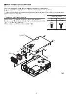
Page 86: ...MW3 XU5000 MT3 XU5500 86 S5 S5 S5 L9 Projection Mechanical Parts List ...

Page 87: ...MW3 XU5000 MT3 XU5500 87 Mechanical Parts List A D D E B C C L19 L13 L5 L8 L18 L11 L1 L3 L7 L12 L6 L14 ...

Page 88: ...07 9233 MOUNTING DUCT LP MA7A M7 610 310 1569 SPACER OP MA7A M8 610 308 1595 SPACER SHEET POWER T MA7A M9 610 310 3334 SPACER SHEET T MA7A M10 610 306 9999 OPTICAL BASE BTM MA7A M11 610 307 0001 OPTICAL BASE TOP A MA7A M12 610 307 0018 OPTICAL BASE TOP B MA7A SCREWS S1 411 031 9304 SCR BIN 3X8 S2 412 066 8706 SPECIAL SCREW S3 411 181 4303 BOLT HEX SCT SW W 2 5X5 S4 411 030 5000 SCR BIN 2X3 S5 411 ...

Page 89: ...MW3 XU5000 MT3 XU5500 89 ...

Page 90: ... MT3A Sep 2003 BB 400 Printed in Japan SANYO Electric Co Ltd ...

Reviews: