background image

INSTRUCTION MANUAL

SRT-612DC

24-Hour Real Time Video Recorder

Please read this manual and accompanying “IMPORTANT SAFETY INSTRUCTIONS” sheet carefully before connecting your
VCR and operating it for the first time.
Be sure to read carefully and follow all the PRECAUTIONS on page 2.
Keep the manual in a safe place for future reference.

NC4QG/U (SRT-612DC GB)  Wed. June, 06/2001

Summary of Contents for SRT-612DC

Page 1: ...l and accompanying IMPORTANT SAFETY INSTRUCTIONS sheet carefully before connecting your VCR and operating it for the first time Be sure to read carefully and follow all the PRECAUTIONS on page 2 Keep the manual in a safe place for future reference NC4QG U SRT 612DC GB Wed June 06 2001 ...

Page 2: ...on for proper heat dissipation Do not block the ventilation holes at the top and bottom of the VCR Do not place the unit on a carpet because this will block the ventilation holes Install the VCR in a horizontal position only Avoid locations subject to strong vibrations Avoid moving the VCR between cold and hot locations see Moisture Condensation Problems this page Do not place the VCR directly on ...

Page 3: ...D INDICATORS 4 CONNECTIONS 7 VIDEO CASSETTE TAPES 8 TYPES OF ON SCREEN DISPLAYS AND DISPLAY SEQUENCE 9 SETTING THE CLOCK AND LANGUAGE 10 CHANGING THE DISPLAY POSITION 11 NORMAL RECORDING 12 AUTOREPEAT RECORDING 14 PROGRAM TIMER RECORDING 15 RECORDING USING AN EXTERNAL TIMER INPUT 17 ALARM RECORDING 18 NORMAL PLAYBACK 20 SPECIAL PLAYBACK 21 SETTING THE SECURITY LOCK 22 SETTING THE SW OUT TERMINAL O...

Page 4: ...L RESET button I TIMER button J REC PLAY SPEED button recording playback speed K TRACKING V STILL button L TRACKING V STILL button M MENU button Press this button to display the menu Buttons I J K and L are used for menu control N ON SCREEN switch O Front door P Digital display panel PLAY REC CHECK REW FF STOP PAUSE SCAN MENU TRACKING V STILL REC PLAY SPEED TIMER ON SCREEN ON OFF MENU RESET ALL RE...

Page 5: ...ard FIELD SHIFT Clog detection indicator Flashes when the recording quality deteriorates due to dirty VCR heads Overwrite inhibit indicator When in MENU 3 SET UP OVERWRITE INHIB is set to Y this indicator flashes when the REC button is pressed and the system is fast forwarding to the counter position where the previous recording was stopped 8 OFF indicator Comes on when the tape end has been reach...

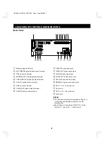
Page 6: ...AUDIO IN audio input jack I AUDIO OUT audio output jack J MIC IN microphone input jack K REMOTE remote control input jack L DC 12 V IN input terminal M Do not use N DC 12 V IN input terminal O Fuse cover NOTES This terminal board may be damaged by 5 kg cm or more torque and using φ6 mm tip or more size screendrivers Pay attention to the polarity of the DC 12 V input terminal red screw black screw ...

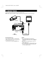
Page 7: ...e DC power cord not supplied To DC power supply About the memory reset If the VCR location is changed or to cancel previous settings please reset the memory as described below The timer and date will be reset To reset the memory press the ALL RESET button NOTES For more details please refer to the manuals accompanying all other devices If the connections are not made properly it may cause a fire o...

Page 8: ...ention tab the VCR will eject the cassette If the TIMER button is pressed when a cassette without erasure prevention tab is loaded the timer recording indicator n will start flashing and a buzzer will sound Erasure prevention tab Loading 1 Place the cassette label side up in the loading slot Gently push the centre of the cassette until it is loaded automatically When the cassette is loaded the cas...

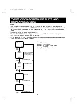
Page 9: ... 20 00 8 Set the ON SCREEN switch to the ON position Press the MENU button First time Press the PAUSE SCAN button MENU 1 Monitor TV screen normal screen DAYLIGHT SET CLOCK SET LANGUAGE SW OUT USED TIME Press the PAUSE SCAN button SET UP Press the PAUSE SCAN button Press the PAUSE SCAN button TIMER SET Press the MENU button Second time Press the MENU button Third time Press the MENU button Fourth t...

Page 10: ...time to standard time F Press the button G Press the l or j button to set the month ex 10 then press the button The day of week is set automatically H Press the l or j button to set the day ex 15 then press the button I Press the l or j button to set the year ex 98 for 1998 then press the button NOTE The last 2 digits only are displayed J Press the l or j button to set the hours ex 15 for 3 PM the...

Page 11: ...CREEN switch to the ON position The date and time are displayed 3 Press the or button The display will move towards the right or the bottom NOTE If the or button is kept pressed for 1 second or more the display will move at a faster speed Date Time display 10 15 98 THU 000 15 20 00 24 NC4QG U SRT 612DC GB Wed June 06 2001 11 ...

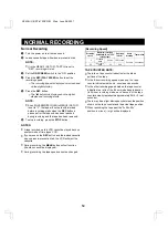
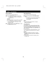
Page 12: ...the loaded cassette has no erasure prevention tab the VCR will eject the cassette During recording the MENU button will not function the menu cannot be displayed During recording the tape speed cannot be changed Recording Speed Recording speed Maximum recording duration with an T 160 cassette tape Recording interval Audio recording Tape motion 8 Standard mode 8 hours 1 60 second Possible Continuou...

Page 13: ... will be rewound and then played back The VCR will then return to the previous recording mode NOTE During recording check operations recording is suspended momentarily Clog Detection The recording quality is monitored automatically When the heads are dirty and the recording quality deteriorates the output at the WARNING OUT terminal becomes 0V Low the a indicator flashes on the digital display and...

Page 14: ...ed the VCR will rewind it to the beginning and recording will resume NOTE Even if OVERWRITE INHIB in MENU3 SET UP is set to Y the tape will not be fast forwarded before recording starts NOTES If during autorepeat recording there is an alarm trigger AL is displayed on the digital display and alarm recording will take place Please refer to page 18 ALARM RECORDING If the REC TAPE END setting is REPEA...

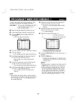
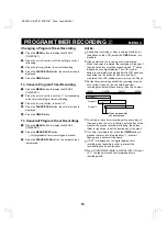
Page 15: ... next to the recording stop time 9 Press the l or j button to set the recording stop minutes ex 00 then press the button The SPD recording speed position will start flashing F Press the l or j button to select the recording speed ex 24 then press the button N will start flashing G Press the l or j button to select Y Y recording will take place N recording will not take place Repeat steps 4 to G to...

Page 16: ... interrupted When the power is restored the recording will resume if the stop time has not yet been reached and will be displayed on the digital display The VCR internal battery is completely recharged after the VCR has been connected to a live outlet for 48 hours and it will maintain all the VCR settings memory for up to 30 days Set the timer recordings so that the recording times do not overlap ...

Page 17: ... is flashing The SPD recording speed position will start flashing 3 Press the l or j button to select the recording speed ex 24 then press the button N will start flashing 4 Press the l or j button to select Y 5 Follow steps H and I under PROGRAM TIMER RECORDING 1 When an external signal is input E will light on the digital display and recording will take place NOTES Other timer recordings using t...

Page 18: ...speed 8H 8 hour mode recording NC Recording at the speed already set 7 Press the PAUSE SCAN button the normal screen is displayed The setting procedure is now completed NOTES During alarm recording all buttons are disabled If OFF is displayed on the digital display alarm recording is not possible in order to prevent the recorded tape to be recorded over If an alarm trigger is received while alarm ...

Page 19: ...he next alarm recording the counter will indicate 000 Connections to the ALARM IN OUT Terminals Alarm input signal Connect a make contact no voltage switch between the ALARM IN and COM terminals Alarm output signal Normally DC 5V are output between the ALARM OUT and the COM terminals When an alarm input trigger is received and the unit is recording the output falls to 0V Once the alarm recording i...

Page 20: ... noise from the picture 5 To stop playback press the STOP button To advance or rewind the tape press the FF or REW button NOTES A tape recorded on another make of time lapse VCR cannot be played back on this unit A tape recorded on this VCR cannot be played back on another make of time lapse VCR Tracking Control If there is noise in the image during playback 1 While looking at the playback picture...

Page 21: ...reduce the vertical rolling of the image 2 If it cannot be corrected press the TRACKING V STILL button Frame Advance 1 Press the FF button during still image mode The still image is advanced of one image field 2 To return to normal playback press the PLAY button Alarm Scan To look for an alarm recording by viewing the first 5 seconds of each alarm recording 1 Press the PAUSE SCAN button during sto...

Page 22: ...utton to display the MENU 2 SW OUT 2 Press the l or j button to set the FIELD or FRAME With each press of the button the setting will change as indicated below NOTE If TIMING is set to FRAME see step 4 FRAME will be indicated instead of FIELD 3 Press the button The TIMING setting starts flashing 4 Press the l or j button to set the TIMING FIELD 1 pulse is output after each set number of fields FRA...

Page 23: ...ode recording NC Recording at the speed already set Action to take when a tape is loaded 7 Press the button The TAPE IN setting starts flashing 8 Press the l or j button to set the desired mode STOP Stays in stop mode REC Goes into recording mode Overwrite inhibition mode Recording end search and recording If OVERWRITE INHIB is set to Y when the REC button is pressed after the recording has been s...

Page 24: ... CLOG DETECT setting starts flashing L Press the l or j button to set the desired mode Y The recording quality is monitored automatically When the heads are dirty and the recording quality deteriorates the output at the WARNING OUT terminal becomes 0V Low the a indicator flashes on the digital display and the buzzer sounds N The recording quality is not monitored M When finished press the PAUSE SC...

Page 25: ...cording a pulse signal is output at the SW OUT terminal after each recording period This terminal is usually connected to the switch input SW IN of devices like a camera switcher unit or a quad compressor REMOTE Jack Remote control of the VCR is possible by connecting a remote controller with a circuit such as indicated below to the REMOTE jack Use a 3 5 mm mini jack type plug The connection shoul...

Page 26: ...e TV monitor is correct 3 Check that the on screen display of the date and time is correct 4 Press the REW button to rewind the recorded tape a few seconds 5 Press the PLAY button and check that the playback image is correct 6 Check that the recorded date and time are correct NOTES If the security lock is engaged it has to be released before proceeding to the inspection If any problem is discovere...

Page 27: ... N is selected for the timer recordings Be sure to select Y for the programmed timer recordings Alarm recording is not possible OFF is displayed on the digital display Press the EJECT STOP FF REW or PLAY button to turn the indicator off Noise in the playback picture The video heads need cleaning Clean the video heads The date and time are not recorded The ON SCREEN switch is set to the OFF positio...

Page 28: ...mode 350 line or more Color mode 300 line or more Audio Input 8 dBs RCA pin jack 27 kΩ unbalanced Output 8 dBs RCA pin jack 600 Ω unbalanced Microphone input 60 dBs 3 5 mm mini jack 10 kΩ unbalanced Connectors Alarm input Contact closes with no voltage Alarm output DC 5 V 0 5 5 7 kΩ Tape end output DC 5 V 0 5 5 7 kΩ Warning output DC 5 V 0 5 5 7 kΩ Switch output DC 5 V 0 5 5 7 kΩ Ext timer input C...

Page 29: ...e This warranty does not apply to uncrating setup installation removal of the product for repair or reinstallation of the product after repair This warranty does not apply to repairs or replacements necessitated by any cause beyond the control of SFC including but not limited to any malfunction defect or failure caused by or resulting from unauthorized service or parts improper maintenance operati...

Page 30: ...21605 Plummer Street 1AC6P1P1448 AB Chatsworth California 91311 NC4QG U 0601KP 01 Issue No 3 Copyright SANYO 1997 All rights reserved Printed in Japan NC4QG U SRT 612DC GB Wed June 06 2001 ...

Reviews: