2009 Sargent & Greenleaf, Inc.
Document 630-809
Revised 2/15/2010
Sargent & Greenleaf, Inc.
Sargent & Greenleaf S.A.
A Wholly Owned Subsidiary of Stanley Security Solutions, Inc.
9, chemin du Croset
PO Box 930, Nicholasville, KY 40356
1024 Ecublens, Switzerland
Phone: (800)-826-7652 Fax: (800)-634-4843
Phone: +41-21 694 34 00
Phone: (859)-885-9411 Fax: (859)-887-2057
Fax: +41-21 694 34 09
Installation Instructions for Model 2007 D•Drive Safe Lock
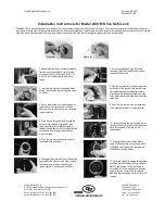
The Model 2007 is a non-handed electronic safe lock. It will be necessary to plug the provided cable into the lock. This is a phone-type connector that will only insert one
way (Figure A). Make sure it is fully inserted and locked into the lock case receptacle. The lock cable must to be routed in the recessed channel in the lock’s cover. Figure B
shows the proper cable placement The cable runs through the opening of the case and on through the safe’s spindle hole to the keypad.
Figure A
Figure B
1. Measure the safe’s door thickness (distance
from the mounting surface for the lock to the
mounting surface for the keypad. Add
¾
” (19
mm), and cut the aluminum spindle to this
length.
2. Insert the lock cable into the spindle slot as
shown. Then slide the cable through the length
of the slot.
3. As you slide the last bit of cable through the
spindle slot, place the spindle into the lock
body cam. The spindle and cam are configured
to mate together.
4. Place the end of the lock cable through the
safe door from inside. Pulling gently on the
cable insert the lock with attached spindle
through the safe door so that it can be attached
to the door’s mounting plate with the three
screws provided.
5. Place the lock cable through the center of
the keypad base as shown.
6. Pulling gently on the cable, move the keypad
base against the safe door, and attach it using
the two machine screws provided. Do not
tighten beyond 15 inch-pounds (1,695 Nm).
7. If not already attached, plug the battery
connector cable into the white receptacle on
the back of the keypad.
8. Plug the lock cable into the black receptacle
on the back of the keypad. Note that there are
two raised ridges on the cable plug and two
matching slots in the keypad receptacle. Align
these features before inserting the plug into the
receptacle.
9. Place the lock cable into the recessed area
of the keypad provided for it on the left side.
10. Place the battery cable through the slot at
the base of the battery cable compartment and
place the remainder of the cable in the
compartment.
11. Keeping the lock cable and the battery
cable in their respective compartments, place
the keypad onto the base. The top seats into
the base first, then the bottom.
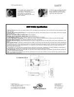
12. Install and tighten the keypad holding screw
as shown. Use the one-way security screw for
EN1300 applications. The Phillips screw is
acceptable for all other applications. Once the
screw is in place, cover it with the self-stick
S&G logo after peeling the protective film off of
the logo.


