


IntelliFlow 3 Liquid Installation Guide
1
875-3000-100 Rev A1
LIQUID INSTALLATION GUIDE
875-3000-100 Rev A1
Overview:
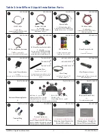
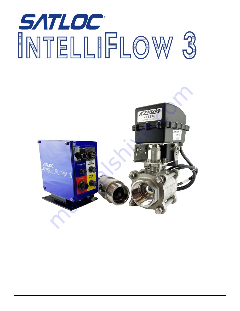
This installation guide lists all the parts in the
IntelliFlow 3 (IF3)
liquid kits
and provides instructions on how to install
the IF3 components, associated cables, and switches.
Read this manual thoroughly before beginning the installation.
If you have any questions, contact your local dealer or Satloc Customer Service.