background image

390G+ INSTALLATION 

INSTRUCTIONS

FORM 39080 REV. E

1

1/2010

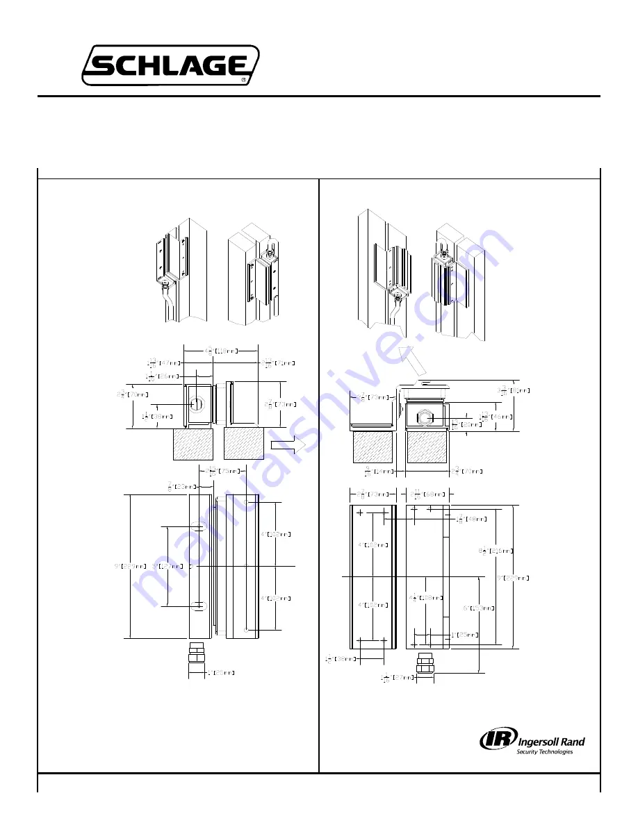
SLIDING GATE APPLICATION TEMPLATE:

SWINGING GATE APPLICATION TEMPLATE:

INSTALLATION CONSIDERATIONS:

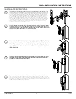
The 390G+ is an electromagnetic lock designed for use on exterior gate applications, though it can be used indoors under circumstances where conduit-enclosed wiring is
desirable or unavoidable. These instructions cover two basic mounting situations: swinging and sliding. Other mounting situations may be encountered which may necessi-
tate fabrication of custom brackets or reinforcements to accommodate the lock. Wiring should be protected by conduit. Wire leads provided are 24 inches long and provi-
sions should be made for connections within that distance. You must determine which type of mounting screws provided will best suit your installation. For light-gauge metal
frames, self tapping screws may be used. If the frame is heavy gauge metal, machine screws may be required to adapt the lock to a particular post or frame. Armature
mounting hardware is provided for direct mounting. The sex nut (provided) can be used instead of the TJ brackets, if  mounting the armature on a standard, 1-3/4” door.
Other sex nuts, of different lengths, are available from Locknetics distributors. Refer to the last page for parts list with pictures.

Schlage Lock Company

575 Birch Street
Forestville, CT 06010
technical support: 866-322-1237
email: SESsupport@irco.com
web: www.irsupport.net

Summary of Contents for 390G+

Page 1: ... leads provided are 24 inches long and provi sions should be made for connections within that distance You must determine which type of mounting screws provided will best suit your installation For light gauge metal frames self tapping screws may be used If the frame is heavy gauge metal machine screws may be required to adapt the lock to a particular post or frame Armature mounting hardware is pr...

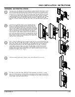
Page 2: ...cause the position of the bracket must be adjustable in the next step Fasten the magnetic lock assembly to the mounting plate using the 2 16 hex wrench provided Mount armature lower TJ bracket assembly to moving part of gate using two 1 4 20 button head sock et cap screws and washers Alternate hardware may be substituted if necessary Close the gate and secure it if such mechanical means exists Wit...

Page 3: ...oles Fasten the assembly with the remaining two 10 screws Center the assembly on the TJ mounting plate and lock into place using two 6 32 set screws A rubber mallet may be used to adjust position if tight Fasten thestandard mounting plate to the magnetic lock using the 3 16 hex wrench provided Mount armature TJ bracket assembly to moving part of gate using four of either 10 flat head self tap ping...

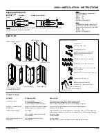
Page 4: ... SOC SET SCREW CUP POINT 1 TJ MOUNTING PLATE 390G MOUNTING HARDWARE KIT UPPER TJ BRACKET STD MOUNTING PLATE MAGNET ASSEMBLY STANDARD OR MAGNET ASSEMBLY MBS TROUBLE SHOOTING PROBLEM POSSIBLE CAUSE RESOLUTION Lock does not lock No power applied Check power at lock then check wiring and power supply AC voltage applied instead of DC Use rectifier on low voltage side Use DC power supply Lock not making...

Reviews: