*77660*
77660
1
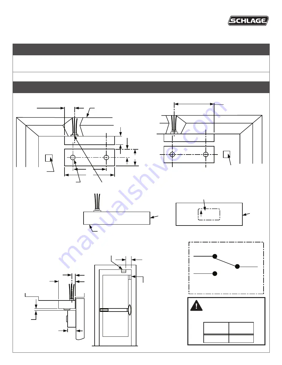
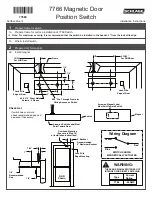
Prepare frame for switch.
1a Prepare frame for surface installation of 7766 Switch.
L
Note: For maximum security, it is recommended that the switch be installed in the header, 2” from the lock stile edge.
1b Wire & install switch.
2
Prepare door for magnet.
2a Install magnet.
Check List
Magnet
Arrow on Magnet Label
Must Point Toward Switch
Arrow on Switch Label Must
Point Toward Door
Switch
Wiring Diagram
Yellow
Blue
Red
SWITCH SHOWN
MAGNETICALLY ACTUATED
Lock Stile
Edge Mounting
RHR
Shown
2” Backset
Recommended
6” Maximum Backset
Overhead Mounting
(See note in Step 1-A
of installation Instructions)
If switch does not work:
check recommended gap and
decrease if necessary.
Lock Stile
Edge of Door
2 13/32”
For RHR Door
1”
1/2”
1/8”
Recommended
Gap
7/32”
3”
2”
1/2”
1/2”
Frame
19/32”
For LHR Door
Lock Stile
Edge of Door
#6 X 3/4” Sheet Metal
Screws - 4 Places
9/32” Dia. Through Frame for
Wiring Access on Switch
1”
WARNING:
THESE ARE SIGNAL SWITCHES. NOT
INTENDED FOR DIRECT SWITCHING.
Type
.25 AMP
7766
Current
Rating
Surface Mount
7766 Magnetic Door
Position Switch
Installation Instructions


