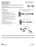
L-Series Electrified Lock Installation Instructions
EL, Electrically Locked (Fail Safe):
Outside knob/lever is continuously locked electrically. Latchbolt is retracted by key
outside or by knob/lever inside. Switch or power failure allows outside knob/lever to retract latchbolt. Auxiliary latch
deadlocks latchbolt when door is closed. Inside knob/lever is always free for immediate exit.
EU, Electrically Unlocked (Fail Secure):
Outside knob/lever is continuously unlocked electrically. Latchbolt is retracted
by key outside or by knob/lever inside. Auxiliary latch deadlocks latchbolt when door is closed. Inside knob/lever is always
free for immediate exit.
Electrical Requirements
• Voltage: 24VAC or 24VDC (Maximum 26V, Minimum 22V)
• Peak Current: Amps 1.3 at 5 to 15 second intervals
• Holding Current: Amps .135 between peak current intervals
• Operating Temperature: M140°F, Minimum -22°F
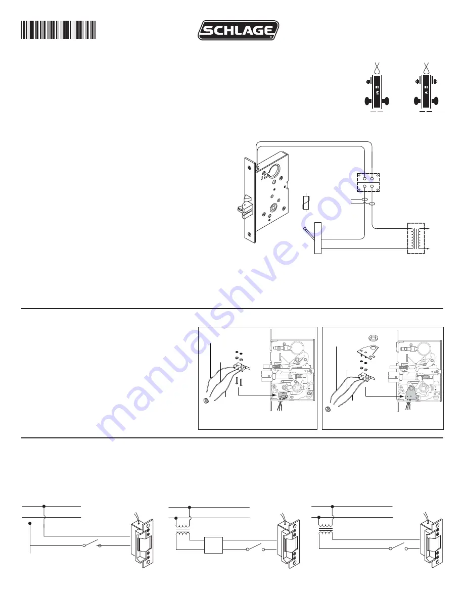
L-Series Typical Installation
Electrified L-Series locks apply full voltage to the solenoid upon initial
application of power and reapply full voltage at 5 −15 second intervals
through a transistorized circuit.
• Each lock should have its own transformer. Two or more locks may
be operated in parallel from a single transformer provided it has the
necessary current rating.
DO NOT
connect locks in series from a higher voltage rated transformer.
Typical Wiring Diagram for Electrified L-Series Locks
Varistor here,
if used
(Not Furnished)
Frame to
Door Connector
(Not Furnished)
Switch
(Not Furnished)
115VAC
Transformer
(Not Furnished)
Electric Latch Release 10-042 Installation Instructions
• 12
Volts
DC
• Not designed for continuous and electrical locking (fail safe), or mortise type latches.
See reverse side for D-Series Electrified Locks
A
LL
INSTALLATIONS
SHOULD
BE
IN
ACCORDANCE
WITH
LOCAL
ELECTRICAL
CODES
AND
N
ATIONAL
E
LECTRICAL
C
ODE
, NFPA 70
P513-541
L9080EL/EU
L9082EL/EU
IMPORTANT!
Connection of locks to a supply circuit containing electromagnetic devices
is not recommended. If used, the resulting transient voltages could damage the lock. The transient voltage must be carefully suppressed at the equipment
producing it before connecting the lock to the same circuit. A varistor rated at 35 V (peak recurrent) may be used for transient voltage protection.
EL/EU Solenoid and Driver Replacement Kit
Order by L283-053
Typical Wiring Diagram
DC Power Source − Silent Operation
12VDC
Switch
(Not Furnished)
Typical Wiring Diagram
AC Power Source − Silent Operation
115VAC
Transformer 12VAC
(Not Furnished)
Rectifier
12VDC
Switch
(Not Furnished)
Typical Wiring Diagram
AC Power Source − Audible Operation
115VAC
Transformer 24VAC
(Not Furnished)
Switch
(Not Furnished)
L-Series Request-to-Exit (RX) Installation Instructions
A microswitch inside the lock case is activated when
the knob/lever is rotated. The switch signals the use of
the opening to security systems. Order by L283-263 for
L-Series locks, and L283-239 for LV-Series locks.
• Use proper wire gauge to minimize voltage drop.
Electrical Requirements
• Amps 0.5 Volts 24 DC
• Operating Temperature: M140°F, Minimum -22°F
All power requirements shown are for single lock operation.
L-Series RX Switch (L283-263)
LV-Series RX Switch (L283-239)
black
(common)
yellow
(NO)
blue
(NC)
black
(common)
yellow
(NO)
blue
(NC)
24VAC


