Content
AZM400
Operating instructions
Solenoid interlock
1
EN
1. About this document
1.1 Function
This operating instructions manual provides all the information you
need for the mounting, set-up and commissioning to ensure the safe
operation and disassembly of the safety switchgear. The operating
instructions must be available in a legible condition and a complete
version in the vicinity of the device.
1.2 Target group: authorised qualified personnel
All operations described in this operating instructions manual must
be carried out by trained specialist personnel, authorised by the plant
operator only.
Please make sure that you have read and understood these operating
instructions and that you know all applicable legislations regarding
occupational safety and accident prevention prior to installation and
putting the component into operation.
The machine builder must carefully select the harmonised standards
to be complied with as well as other technical specifications for the
selection, mounting and integration of the components.
1.3 Explanation of the symbols used
Information, hint, note:
This symbol is used for identifying useful additional information.
Caution:
Failure to comply with this warning notice could
lead to failures or malfunctions.
Warning:
Failure to comply with this warning notice could
lead to physical injury and/or damage to the machine.
1.4 Appropriate use
The products described in these operating instructions are developed to
execute safety-related functions as part of an entire plant or machine. It
is the responsibility of the manufacturer of a machine or plant to ensure
the correct functionality of the entire machine or plant.
The safety switchgear must be exclusively used in accordance with
the versions listed below or for the applications authorised by the
manufacturer. Detailed information regarding the range of applications
can be found in the chapter "Product description".
1.5 General safety instructions
The user must observe the safety instructions in this operating
instructions manual, the country specific installation standards as well
as all prevailing safety regulations and accident prevention rules.
1.2
Target group: authorised qualified personnel
. . . . . . . . . . . . . . . . . .1
1.3 Explanation of the symbols used . . . . . . . . . . . . . . . . . . . . . . . . . . .1
1.4 Appropriate use . . . . . . . . . . . . . . . . . . . . . . . . . . . . . . . . . . . . . . . .1
1.5 General safety instructions . . . . . . . . . . . . . . . . . . . . . . . . . . . . . . .1
1.6 Warning about misuse . . . . . . . . . . . . . . . . . . . . . . . . . . . . . . . . . . .2
1.7 Exclusion of liability . . . . . . . . . . . . . . . . . . . . . . . . . . . . . . . . . . . . .2
2.1 Ordering code . . . . . . . . . . . . . . . . . . . . . . . . . . . . . . . . . . . . . . . . .2
2.2 Special versions. . . . . . . . . . . . . . . . . . . . . . . . . . . . . . . . . . . . . . . .2
2.3 Comprehensive quality insurance to 2006/42/EC . . . . . . . . . . . . . .2
2.4 Purpose . . . . . . . . . . . . . . . . . . . . . . . . . . . . . . . . . . . . . . . . . . . . . .2
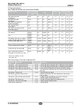
2.5 Technical data . . . . . . . . . . . . . . . . . . . . . . . . . . . . . . . . . . . . . . . . .3
2.6
. . . . . . . . . . . . . . . . . . . . . . . . . . . . . . . . . . . .3
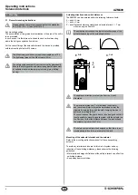
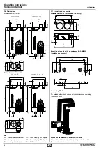
3 Mounting
3.1 General mounting instructions . . . . . . . . . . . . . . . . . . . . . . . . . . . . .4
3.2 Manual release . . . . . . . . . . . . . . . . . . . . . . . . . . . . . . . . . . . . . . . .5
3.3 Electrical manual release - E (for -ST2). . . . . . . . . . . . . . . . . . . . . .5
3.4 Emergency exit -T . . . . . . . . . . . . . . . . . . . . . . . . . . . . . . . . . . . . . .5
3.5 Assembly with mounting set . . . . . . . . . . . . . . . . . . . . . . . . . . . . . .5
3.6 Dimensions . . . . . . . . . . . . . . . . . . . . . . . . . . . . . . . . . . . . . . . . . . .6
3.7 Actuator and accessories. . . . . . . . . . . . . . . . . . . . . . . . . . . . . . . . .6
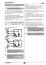
4 Rear side Electrical connection
4.1 General information for electrical connection. . . . . . . . . . . . . . . . . .7
4.2 Control options in the normal operating mode. . . . . . . . . . . . . . . . .7
4.3 Requirements for the connected safety-monitoring module . . . . . .7
5 Operating principles and coding
5.1 Mode of operation of the safety outputs. . . . . . . . . . . . . . . . . . . . . .8
5.2 Actuator teaching / actuator detection . . . . . . . . . . . . . . . . . . . . . . .8
6.1 Diagnostic-LEDs . . . . . . . . . . . . . . . . . . . . . . . . . . . . . . . . . . . . . . .8
6.2 Diagnostic information . . . . . . . . . . . . . . . . . . . . . . . . . . . . . . . . . . .9
7.1 Functional testing. . . . . . . . . . . . . . . . . . . . . . . . . . . . . . . . . . . . . .10
7.2 Maintenance . . . . . . . . . . . . . . . . . . . . . . . . . . . . . . . . . . . . . . . . .10
8.1 Disassembly. . . . . . . . . . . . . . . . . . . . . . . . . . . . . . . . . . . . . . . . . .10
8.2 Disposal . . . . . . . . . . . . . . . . . . . . . . . . . . . . . . . . . . . . . . . . . . . . .10
9 Appendix
9.1
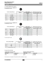
Wiring configuration and accessories
. . . . . . . . . . . . . . . . . . . . . . 11
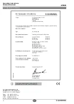
10 EU Declaration of conformity
x.000 / 09.2017 / v
.A. - 103016610-EN /
A / 2017-09-07 /
AE-Nr
. -
EN
Operating instructions. . . . . . . . . . . .pages 1 to 12
Original


