background image


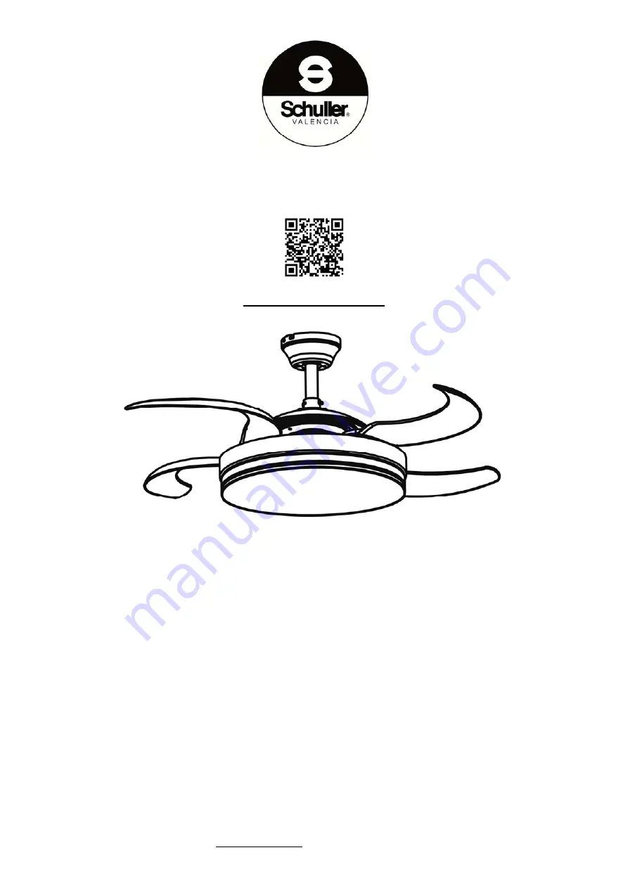
VENTILADOR DE TECHO CON LUZ LED  "VENTO" 

168342 


MANUAL DE USUARIO. 


Luz LED CCT 3000k a 6000K( LUZ CÁLIDA, NEUTRA Y FRIA) 

Ventilador con motor DC de 6 velocidades e inversión de giro. 

Aspas escamoteables en acrílico transparente.  

Función  temporizador. 
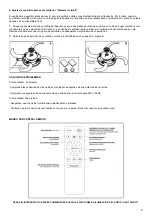
Mando a distancia. 


NOTA 

SCHULLER RECOMIENDA LA COLOCACIÓN DE PROTECTORES DE SOBRETENSIÓN PARA EVITAR LOS DAÑOS EN 

LOS COMPONENTES ELECTRÓNICOS DE LA LUMINARIA LED. 

Disponibles en nuestro catálogo 


Para cualquier duda técnica póngase en contacto con nuestro Departamento Técnico. 

Estamos a su servicio en nuestro email irodriguez@schuller.es o en nuestro teléfono 961 601 051 Ext. 229 


Rev.10.21 

Summary of Contents for 168342

Page 1: ...arente Función temporizador Mando a distancia NOTA SCHULLER RECOMIENDA LA COLOCACIÓN DE PROTECTORES DE SOBRETENSIÓN PARA EVITAR LOS DAÑOS EN LOS COMPONENTES ELECTRÓNICOS DE LA LUMINARIA LED Disponibles en nuestro catálogo Para cualquier duda técnica póngase en contacto con nuestro Departamento Técnico Estamos a su servicio en nuestro email irodriguez schuller es o en nuestro teléfono 961 601 051 E...

Page 2: ... onentes aje ntes del Canop ector del cuerpo ador ación LED alación incluido emoto l soporte de m os en el techo a techo de obr priételo con las ventilador debe realizada por un s no toque la cu DE INSTALAC í 2A Corto y 2 o de ventilador o imanes y torni montaje o con una prof ra o 4 balanci s tuercas hast 1 SOPOR e ser de 220 V n profesional cu uchilla cuando e CIÓN 2B largo llos undidad adec ine...

Page 3: ... drive ED centrado ar la altura des onado si no es el tubo y en el aro de unión s de él previam del aro hasta o Cubra el ar oporte de mon n el aro de circ r mediante los en la cara inf seada del ven stá ya pre inst orden indicad situado en la mente Gírelo inmovilizar el ro de unión co ntaje y gire el cuito LED intro s tornillos inclu ferior del cuerp ntilador talada Usand do en el esque parte supe...

Page 4: ... que salen del ventilador por la parte superior Después conecte el cable de red con los cables INPUT del Módulo Una vez conectados todos introduzca el módulo en el espacio reservado en el soporte de montaje del techo 8º Levante el canopí hasta el techo para cubrir el soporte de montaje asegúrese que el canopí se asiente en los dos tornillos del soporte gire el canopí para asegurarse que la cabeza ...

Page 5: ...l problema de oscilación aún se nota Repita esto hasta encontrar el lugar que permitirá que desaparezca el problema de la oscilación 2º Quite las piezas del imán de equilibrio y coloque la tira adhesiva en su posición Figura B SOLUCIÓN DE PROBLEMAS Si el ventilador no arranca Compruebe las conexiones de los cables al ventilador asegúrese de que estén todas correctas Compruebe y asegúrese de que la...

Page 6: ...table blades in clear acrylic Timer function Remote control NOTE SCHULLER RECOMMENDS TO PLACE SURGE PROTECTORS TO AVOID DAMAGES TO THE ELECTRONIC COMPONENTS OF THE LED LUMINAIRE Available in our catalogue If you have any technical questions please do not hesitate to contact our technical Department We are at your disposal in our emai irodriguez schuller es Rev 10 21 ...

Page 7: ...a power i allation should b injury do not to AND INSTALL nents acket s 2A short y e ylic diffuser stallation tools the ceiling m deep holes int ng mount brac nput of 220 V be carried out b uch the blades LATION STEP 2B long including magn mount bracke to the ceiling cket onto the e 1 CEIL 50 HZ by a qualified ele while the fan is PS nets and screws et using a 8mm expansion bolt LING MOUNT B ectric...

Page 8: ... the semi sp ed onto the LE r using the sc o use accordin he pin and set er onto the tub om the connec rough the tube be is firmly fix with the conne phere on the m ED board by in rews provided ng to the desir screw to inse be in the orde ctor ring place e Rotate until xed in place ti ctor cover mounting brac nserting their p d red height of th ert the hemisp r indicated in ed in the uppe the hole...

Page 9: ...the ideal placement 7º Next to the ceiling bracket connect the module to the wires that come out from the top downrod topside Then connect the network cable to the INPUT cables of the module Once all are connected insert the module into the reserved space on the ceiling mount 8º Raise the canopy to the ceiling to cover the ceiling mount ensuring the canopy rests on the two bracket screws rotate th...

Page 10: ...epeat this until you find the position that corrects the wobble and allows the fan to run smoothly 2º Remove the balance magnets and attach the balance kit in order to stick them in place Figure B TROUBLESHOOTING 1 The fan won t start Check the fan wiring ensure all the cables are connected correctly Check and ensure that the input power is correct at 220V 50HZ 2 The fan makes a loud noise Ensure ...

Reviews: