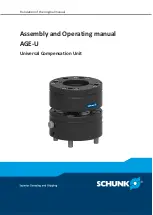
SCHUNK AGE-U, Assembly And Operating Manual
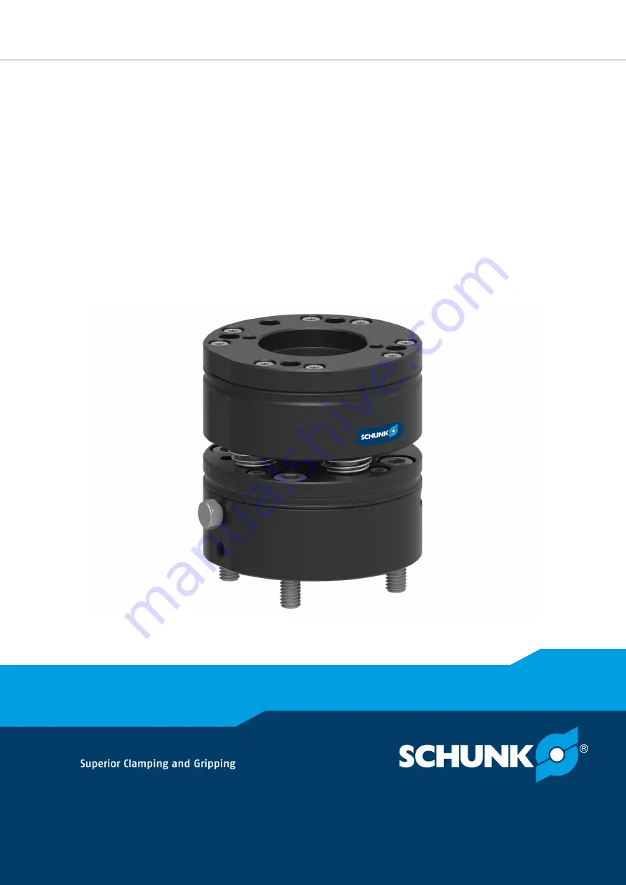
The SCHUNK AGE-U is a versatile robot gripper that provides precise and powerful gripping capabilities. Ensure optimal performance by referring to the Assembly and Operating Manual available for free download on our website. Master your machine today with this comprehensive manual from 88.208.23.73:8080.
Share
Download

Reviews:
No comments
Related manuals for AGE-U

DS-1
Brand: Yoshitake Pages: 11

JE Series
Brand: VARISCO Pages: 24

KT-2
Brand: WARPP Pages: 28

EVOMAX 2 30
Brand: Ideal Heating Pages: 16

VF100e
Brand: ALL-FILL Pages: 32

MERLIN N Series
Brand: Meheen Pages: 24

IQAN-LC5-C0 Series
Brand: Parker Pages: 40

V3 Optical
Brand: Perun Airsoft Pages: 8

RBK-X1
Brand: TE Connectivity Pages: 15

BB7000
Brand: Climax Pages: 12

FMC-EB Series
Brand: Reer Pages: 4

Chopper 6500 SK30
Brand: Jäger Pages: 40

DataSmart 763
Brand: Harris Pages: 58

K-3864
Brand: Tronair Pages: 11

CoverPro 3000 PROFESSIONAL
Brand: Janome Pages: 58

HIS-ML15-***E Series
Brand: Hope Industrial Systems Pages: 24

OSHA 1926.502
Brand: DBI SALA Pages: 32

CUB12
Brand: newsteo Pages: 15


