background image

Translation of Original Operating Manual

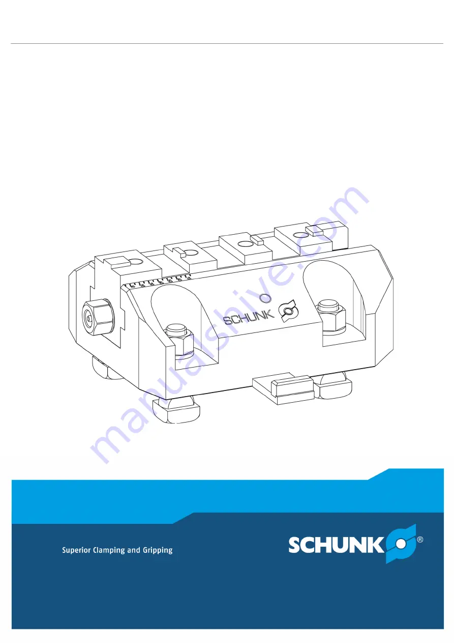
Jaw boxes SPK

Assembly and Operating Manual

Summary of Contents for SPK 140

Page 1: ...Translation of Original Operating Manual Jaw boxes SPK Assembly and Operating Manual ...

Page 2: ... en Dear Customer thank you for trusting our products and our family owned company the leading technology supplier of robots and production machines Our team is always available to answer any questions on this product and other solutions Ask us questions and challenge us We will find a solution Best regards Your SCHUNK team Customer Management Tel 49 7572 7614 1300 Fax 49 7572 7614 1039 customerce...

Page 3: ...the required clamping force in case of a given rpm 19 6 2 2 Calculation example Required initial clamping force Fsp0 for a given rpm n 22 6 2 3 Calculation example permissible RPM for a given effective clamping force 23 6 3 Grades of Accuracy 24 6 4 Permissible imbalance 24 7 Attachment of the jaw boxes 25 7 1 Preparing the installation 25 7 2 Mounting the jaw boxes 26 7 3 Adjustment of the jaw bo...

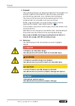
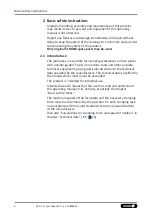
Page 4: ...sed on Illustrations in this manual are provided for basic understanding of the product and may differ from the actual product design We accept no liability for damage resulting from the failure to observe and comply with this operating manual 1 1 Warnings The following key words and symbols are used to highlight dangers DANGER It threatens an immediate danger Non observance will result in death o...

Page 5: ...siness Catalog data sheet of the purchased product Calculation of the jaw centrifugal forces Technology chapter in the lathe chuck catalog The documents marked with an asterisk can be downloaded on our homepage schunk com 5 04 00 Jaw boxes SPK en 0889015 ...

Page 6: ...ith parallel guided T slots on machine tools and other suitable technical equipment paying particular attention to the technical data specified by the manufacturer The technical data specified by the manufacturer must never be exceeded The product is intended for industrial use Intended use also means that the user has read and understood this operating manual in its entirety especially the chapte...

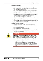
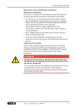
Page 7: ...o be used with it 2 3 Notes on particular risks This product may pose a danger to persons and property if for example It is not used as intended It is not installed or maintained properly The safety and installation instructions local applicable safety and accident prevention regulations or the EC Machinery Directive are not observed DANGER Possible risk of fatal injury to operating personnel if a...

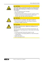
Page 8: ... when working on the machine and the jaw box WARNING Risk of injury due to dropping the jaw box during transport installation or removal Take special care in the danger zone when transporting installing or removing the jaw box Note the relevant load securing regulations for working safely with cranes ground conveyors lifting gear and load handling equipment CAUTION Risk of slipping or falling if t...

Page 9: ...cal equipment CAUTION Risk of burns due to workpieces with high temperatures Wear protective gloves when removing the workpieces Automatic loading is preferred CAUTION Hazard from vibration due to imbalanced rotating parts and noise generation Physical and mental strains due to imbalanced workpieces and noise during the machining process on the clamped and rotating workpiece Ensure the jaw box s a...

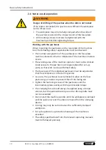
Page 10: ...chine operator must not be limited Good access to the jaw box must be guaranteed for set up work so that work can be performed safely The base jaws of the individual jaw boxes must be adjusted so that the workpiece is in the turning center As a rule the jaw boxes must be locked in place on the face plate using a crossbar to prevent them from falling out Tighten the fastening screws of the jaw boxe...

Page 11: ...the greasing areas To ensure correct distribution of the grease move the mechanism to its end positions several times with the spanner wrench Safety notes for servicing Follow all the applicable legal standards for health and safety during servicing Use suitable personal protective equipment especially protective gloves goggles and safety boots paying particular attention to the operating system a...

Page 12: ...uck jaws Fasten the mounting screws so as to achieve the greatest possible effectiveness At high speeds the jaw boxes may only be used with robust protective equipment If the clamping device is involved in a collision it must be subjected to a crack test before using it again Damaged parts must be replaced with original SCHUNK spare parts Renew the mounting bolts on the chuck jaws if there are sig...

Page 13: ...t safety rules are obeyed by the persons asked to operate maintain and repair the jaw box Monitoring the behavior of personnel The operator must at least occasionally check that the personnel are behaving in a safety conscious manner and are aware of the potential hazards Danger signs The operator must ensure that the signs concerning safety and hazards mounted on the machine where the jaw box is ...

Page 14: ... 00 Jaw boxes SPK en 0889015 2 7 Using personal protective equipment When using this product you must comply with the relevant health and safety at work rules and you must use the required personal safety equipment minimum category 2 ...

Page 15: ...owing conditions Observe the applicable documents 1 2 5 Observe the ambient conditions and operating conditions Observe the maximum number of clamping cycles 6 18 Observe the specified maintenance and lubrication intervals 9 30 Parts touching the workpiece and wear parts are not included in the warranty 15 04 00 Jaw boxes SPK en 0889015 ...

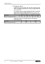
Page 16: ...crew quality 8 8 Or mounting screws according to DIN EN ISO 4762 in conjunction with nuts for T slots according to DIN 508 Screw quality 10 9 Applies to the mounting of jaw boxes on face plates with T slots Screw size M16 M20 M24 M30 Tightening torques MA Nm 150 308 530 1053 Tightening torques for mounting top jaws on the jaw box Screw quality 12 9 Screw size M16 M20 Tightening torques MA Nm 200 3...

Page 17: ...e or base jaw with fine serration and T slot 2 Eye bolts DIN 580 1 Operating manual Scope of delivery Assembly accessories for jaw box suitable for machines with T slots according to DIN 650 4 Screws for T slots DIN 787 or screws DIN EN ISO 4762 4 Collar nuts DIN 55027 or nuts DIN 6331 M30 2 T nuts flat or fixed incl Screws 17 04 00 Jaw boxes SPK en 0889015 ...

Page 18: ... speed of rotation for jaw boxes on face plates CAST IRON face plate with 4 jaw boxes STEEL face plate with 4 jaw boxes Face plates Ø mm Max rotation speed min 1 Face plates Ø mm Max rotation speed min 1 800 430 800 720 900 380 900 640 1 000 340 1 000 570 1 100 312 1 100 520 1 200 290 1 200 480 1 300 265 1 300 440 1 400 245 1 400 410 1 500 230 1 500 410 1 600 215 1 600 380 1 800 190 1 800 340 2 00...

Page 19: ...rsAB Center of gravity radius of top jaw m mAB Mass of one top jaw kg ssp Safety factor for clamping force mB Mass of chuck jaw set kg sz Safety factor for machining Mc Centrifugal force torque Kgm Σs Max clamping force of chuck N 6 2 1 Calculation of the required clamping force in case of a given rpm The initial clamping force Fsp0 is the total force impacting radially on the workpiece via the ja...

Page 20: ... minimum clamping force The workpiece will be uncontrollably released in this area Speed of rotation Clamping force Centrifugal force Effective clamping force Minimum required clamping force Initial clamping force during shutdown Reduction in effective clamping force by the magnitude of the total centrifugal force for gripping from the outside inwards The required effective clamping force for mach...

Page 21: ...cordance with DIN EN 1550 the centrifugal force may be a maximum of 67 of the initial clamping force The formula for the calculation of the total centrifugal force Fc is For this n is the given speed of rotation in RPM The product mB rs is referred to as the centrifugal force torque Mc In case of jaw boxes with split chuck jaws i e with base jaws and top jaws for which the base jaws change their r...

Page 22: ...Center of gravity radius of top jaw rsAB 0 107 m application specific Safety factor Sz 1 5 according to VDI 3106 Safety factor Ssp 1 5 according to VDI 3106 Note Masses of the jaw mounting screws and T nuts are not taken into account First the required effective clamping force Fsp is calculated using the machining force stated Initial clamping force during shutdown Calculation of total centrifugal...

Page 23: ...ible RPM for a given effective clamping force The following data is known from previous calculations Initial clamping force during shutdown Fsp0 17723 N Machining force for machining job Fspz 3000 N application specific Total centrifugal torque of all jaws Mc 2 668 kgm Safety factor Sz 1 5 according to VDI 3106 Safety factor Ssp 1 5 according to VDI 3106 NOTE Masses of the jaw mounting screws and ...

Page 24: ...ncing quality class 6 3 according to DIN ISO 21940 11 Residual imbalance risks may arise due to insufficient rotation compensation being achieved see DIN EN 1550 6 2 e This applies in particular to high speeds of rotation asymmetrical workpieces or the use of lathe chucks that do not correspond to balancing grade 6 3 as well as uneven lubricant application In order to prevent damage resulting from...

Page 25: ...unting screws and T nuts so that the jaw box does not move or twist on the face plate when under load The crosswise slots of the face plate must be clean and free of damage to guarantee form fitting locking with the crossbar of the clamping device The slot depth must be sufficiently deep enough for the crossbar to be able to move freely Check the locking slide of the jaw box and the assembly acces...

Page 26: ...sbar in one of the alternately arranged labyrinth grooves of the face plate 6 Tighten the mounting screws evenly with the permissible torque 4 16 7 3 Adjustment of the jaw boxes on the face plate The number and position of the jaw boxes on the face plate must be selected so that no imbalance of the machine structure occurs The base jaws of the individual jaw boxes must be adjusted so that the work...

Page 27: ... plate in the longitudinal direction using T nuts or a crossbar to prevent it from moving In the lateral direction the intermediate plate must be aligned on the face plate using T nuts and secured to prevent it from twisting 6 The face plate and the corresponding intermediate plate can be equipped with crosswise slots for locking the crossbar used when positioning the jaw box on the face plate Thi...

Page 28: ...kpiece If the base jaw is completely retracted the rear end face is flush with the end face of the base body The scale provided makes it easier to set the chuck jaws of all jaw boxes mounted on the face plate equally 8 2 Important notes When gripping the spindle do not tighten with an extension pipe or using hammer blows Do not place your entire weight on the spanner wrench or stand on it Clamp th...

Page 29: ...ll mounting screws must also be tightened with the maximum permissible tightening torque 4 16 8 3 Checking the jaw boxes The condition of the clamping device should be checked regularly After installation on the machine the jaws of all jaw boxes must be easy to move The spindle and the jaw drive of each jaw box must turn smoothly If the base jaw is stiff when mounted the base body was screwed on i...

Page 30: ... jaw box during transport installation or removal During transport and when installing or removing the jaw box secure it to prevent it from falling First remove the jaw box from the face plate of the lathe 1 Loosen the mounting screws of the SPK evenly 2 For transport screw in an eye bolt 3 Release the locking device with the face plate pushing the crossbar to the center position 4 Extend the SPK ...

Page 31: ...s fastened with a bearing bolt item 6 First remove the safety ring item 12 and then pull out the bearing bolt item 6 The bearing bolt has a pull off thread During disassembly and assembly please take care that the safety ring item 12 does not become damaged or deformed Clean and degrease all parts carefully and check all parts for wear and damage Only use original SCHUNK spare parts when replacing...

Page 32: ...re contamination Approx 1000 operating hours Full cleaning with disassembly of jaw box depending on type of contamination and quantity Using a hand press lubricate the moving parts such as the spindle item 4 and the spindle holding nut item 3 using the tapered grease nipple item 15 in the spindle hexagon item 4 Lubricate the jaw box between the rear jaw position and up to half the jaw stroke posit...

Page 33: ...400 1 3 1515507 Spindle holding nut 1 4 1515509 Spindle 1 5 1515510 Seat of bearing 1 6 1515512 Bearing bolt 1 7 1515514 Slide 1 8 1515515 Bracket 1 9 9966359 O ring DIN 3771 NBR 70 20 0 x 2 5 1 10 9907032 Spring loaded rotary piece 1 11 9907032 Screw DIN EN ISO 4762 M8 x 25 10 9 4 12 9935533 Safety ring DIN 472 30 x 1 2 1 13 9900325 Screw DIN 7984 M6 x 10 2 14 9664002 Countersunk screw DIN EN ISO...

Page 34: ...27 0 x 2 5 1 10 9907023 Compression spring VD 132 D 0 8 x 5 6 L0 43 0 1 11 9907336 Screw DIN EN ISO 4762 M10 x 25 10 9 4 12 9935533 Safety ring DIN 472 30 x 1 2 1 13 9900325 Screw DIN 7984 M6 x 10 2 14 9664002 Countersunk screw DIN EN ISO 10642 M6 x 12 2 15 9905437 Conical lubrication nipple 1 16 9629007 Steel ball hardened Ø 6 0 1 30 0158103 Screw M16 x 40 fine thread 2 SPK 180 SV 3 32 x 90 25 5 ...

Page 35: ...ring VD 132 D 0 8 x 5 6 L0 43 0 1 11 9907240 Screw DIN EN ISO 4762 M12 x 25 10 9 4 12 9621008 Safety ring DIN 472 30 x 1 2 1 13 9900325 Screw DIN 7984 M6 x 10 2 14 9664002 Countersunk screw DIN EN ISO 10642 M6 x 12 2 15 9905437 Conical lubrication nipple 1 16 9629007 Steel ball hardened Ø 6 0 1 30 9660086 Screw DIN EN ISO 4762 M20 x 50 12 9 2 SPK 220 SV 3 32 x 90 30 H7 NS 240 S T Item ID number De...

Page 36: ...0 0 x 2 1 10 9907023 Compression spring VD 132 D 0 8 x 5 6 L0 43 0 1 11 9907240 Screw DIN EN ISO 4762 M12 x 25 10 9 4 12 9621008 Safety ring DIN 472 30 x 1 2 1 13 9900325 Screw DIN 7984 M6 x 10 2 14 9664002 Countersunk screw DIN EN ISO 10642 M6 x 12 2 15 9905437 Conical lubrication nipple 1 16 9629007 Steel ball hardened Ø 6 0 1 30 9660086 Screw DIN EN ISO 4762 M20 x 50 12 9 2 SPK 260 SV3 32 x 90 ...

Page 37: ... 6331 M24 4 19 SNT001339 Flat T nut for size 28 slot 2 20 9907272 Screw DIN EN ISO 4762 M6 x 16 10 9 2 SPK 220 assembly accessories ID number 0899130 suitable for machines with T slots DIN 650 M20 x 22 Item ID number Designation Quantity 17 9984760 Screw for T slot DIN 787 M20 x 22 x 80 8 8 4 18 9980035 Collar nut DIN 6331 M20 4 19 9985273 Flat T nut for size 22 slot 2 20 9907272 Screw DIN EN ISO ...

Page 38: ...8 x 100 8 8 4 18 9980036 Collar nut DIN 6331 M24 4 19 SNT001339 Flat T nut for size 28 slot 2 20 9907272 Screw DIN EN ISO 4762 M6 x 16 10 9 2 ID number 0899145 suitable for machines with T slots DIN 650 M30 x 36 Item ID number Designation Quantity 17 SNT001392 Screw DIN EN ISO 4762 M30 x 90 10 9 4 18 SNT001393 Nut DIN 508 M30 x 36 4 19 SNT001391 Flat T nut for size 36 slot 2 20 9907272 Screw DIN E...

Page 39: ...Assembly drawing 11 Assembly drawing 39 04 00 Jaw boxes SPK en 0889015 ...

Page 40: ... Manual H D SCHUNK GmbH Co Spanntechnik KG Lothringer Str 23 D 88512 Mengen Tel 49 7572 7614 0 Fax 49 7572 7614 1099 info de schunk com schunk com Folgen Sie uns I Follow us 09 2022 2022 SCHUNK GmbH Co KG 04 00 Jaw boxes SPK en 0889015 ...

Reviews: