background image

Original Operating Manual

Assembly and Operating Manual
SRU-plus-D

Pneumatic swivel unit

Summary of Contents for SRU-plus-D

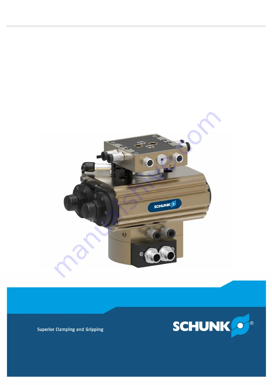
Page 1: ...Original Operating Manual Assembly and Operating Manual SRU plus D Pneumatic swivel unit ...

Page 2: ...ersion 04 00 11 01 2022 en Dear Customer thank you for trusting our products and our family owned company the leading technology supplier of robots and production machines Our team is always available to answer any questions on this product and other solutions Ask us questions and challenge us We will find a solution Best regards Your SCHUNK team Customer Management Tel 49 7133 103 2503 Fax 49 713...

Page 3: ...2 6 Personnel qualification 11 2 7 Personal protective equipment 12 2 8 Notes on safe operation 12 2 9 Transport 13 2 10 Malfunctions 13 2 11 Disposal 13 2 12 Fundamental dangers 13 2 12 1 Protection during handling and assembly 14 2 12 2 Protection during commissioning and operation 14 2 12 3 Protection against dangerous movements 15 2 12 4 Protection against electric shock 15 2 13 Notes on parti...

Page 4: ...ate piston chambers 49 7 Troubleshooting 52 7 1 Product does not move smoothly to the end positions 52 7 2 Product does not travel through the rotating angle 52 7 3 Product rotates jerkily 52 7 4 Product does not move 53 7 5 Torque is diminishing 53 8 Maintenance 54 8 1 Maintenance interval 54 8 2 Lubricants Lubrication points basic lubrication 55 8 3 Inspect and set shock absorbers 55 8 3 1 Inspe...

Page 5: ... 2 Dismantle and assemble rotary actuator center position locked center position 62 8 6 3 Dismantling and assembling rotary actuator fluid feed through 63 9 Translation of original declaration of incorporation 64 10 Annex to Declaration of Incorporation 65 5 04 00 SRU plus D Assembly and Operating Manual en 1380765 ...

Page 6: ...ions in this manual Illustrations in this manual are provided for basic understanding and may differ from the actual product design In addition to these instructions the documents listed under 1 1 2 7 are applicable 1 1 1 Presentation of Warning Labels To make risks clear the following signal words and symbols are used for safety notes DANGER Danger for persons Non observance will inevitably cause...

Page 7: ... 90 SRU plus D Rotating angle 180 SRU plus D End position adjustability 3 SRU plus D with fluid feed through SRU plus D With pneumatic center positioning M SRU plus D With locked center position VM SRU plus D With electrical feed through EDF 1 2 Warranty If the product is used as intended the warranty is valid for 24 months from the ex works delivery date under the following conditions Observe the...

Page 8: ...40 50 60 Without fluid feed through 5514981 5518653 5514989 5514993 5514997 5515001 With fluid feed through 5514982 5518654 5514990 5514994 5514998 5515002 With center position 5516590 5518657 5516594 5516596 5516598 5516600 With locked center position 5514983 5518655 5514991 5514995 5514999 5515003 With fluid feed through and center position 5516591 5518658 5516595 5516597 5516599 5516601 With fl...

Page 9: ...enter position 5519789 5519793 5519799 5519801 5519805 5519809 5519813 With fluid feed through 0371003 0371007 5518599 0371011 0371015 0371019 0371023 With fluid feed through and center position 5519790 5519794 5519796 5519802 5519806 5519810 5519814 With fluid feed through and locked center position 5519791 5519795 5519797 5519803 5519807 5519811 5519815 ID no Seal kit SRU plus D with EDF 20 25 3...

Page 10: ...d with The product is intended for industrial and industry oriented use Appropriate use of the product includes compliance with all instructions in this manual 2 2 Not intended use Inappropriate use includes using the product as a cutting tool or drilling tool for example Any utilization that exceeds or differs from the appropriate use is regarded as misuse 2 3 Constructional changes Implementatio...

Page 11: ...orking with the product the personnel must have read and understood the complete assembly and operating manual Observe the national safety regulations and rules and general safety instructions The following personal qualifications are necessary for the various activities related to the product Trained electrician Due to their technical training knowledge and experience trained electricians are abl...

Page 12: ... goggles when handling hazardous substances Wear close fitting protective clothing and also wear long hair in a hairnet when dealing with moving components 2 8 Notes on safe operation Incorrect handling of the personnel Incorrect handling and assembly may impair the product s safety and cause serious injuries and considerable material damage Avoid any manner of working that may interfere with the ...

Page 13: ...after a malfunction to establish whether it still functions properly and no increased risks have arisen 2 11 Disposal Handling of disposal The incorrect handling of disposal may impair the product s safety and cause serious injuries as well as considerable material and environmental harm Follow local regulations on dispatching product components for recycling or proper disposal 2 12 Fundamental da...

Page 14: ... prevention rules Use suitable assembly and transport equipment and take precautions to prevent jamming and crushing Incorrect lifting of loads Falling loads may cause serious injuries and even death Stand clear of suspended loads and do not step into their swiveling range Never move loads without supervision Do not leave suspended loads unattended 2 12 2 Protection during commissioning and operat...

Page 15: ...nd protective fence must be rigid enough to withstand the maximum possible movement energy EMERGENCY STOP switches must be easily and quickly accessible Before starting up the machine or automated system check that the EMERGENCY STOP system is working Prevent operation of the machine if this protective equipment does not function correctly 2 12 4 Protection against electric shock Possible electros...

Page 16: ... WARNING Risk of injury due to unexpected movements If the power supply is switched on or residual energy remains in the system components can move unexpectedly and cause serious injuries Before starting any work on the product Switch off the power supply and secure against restarting Make sure that no residual energy remains in the system WARNING Risk of injury from sharp edges and corners Sharp ...

Page 17: ...ior of the product is undefined Cutting off the compressed air supply in an uncontrolled manner could lead to undefined states and behavior This may cause personal injury or material damage The operator must define suitable emergency stop and restarting strategies Emergency stop strategies e g by means of controlled shut down Restarting strategies e g using pressure build up valves or suitable val...

Page 18: ...pe of damping method W Soft Angle of rotation 90 180 End position adjustability 3 Center position none M pneumatic VM locked Fluid feed through none 4 4 channels for sizes 20 35 8 8 channels for sizes 40 60 Electrical feed through none M8 M8 connector on the rotating side M12 M12 connector on the rotating side Mounting kit for inductive proximity switch AS Type key ...

Page 19: ...DF data Designation Value Max voltage V 24 Max current per wire A 1 Maximum transmission rate PROFIBUS MBaud 1 5 The catalog data sheet contains diagrams for designing the maximum permissible mass moment of inertia The SCHUNK contact person provides support for designing further applications More technical data is included in the catalog data sheet Whichever is the latest version 19 04 00 SRU plus...

Page 20: ...Back stops 0 180 10 Pinion for fluid feed through 3 Back stops 0 90 12 Monitoring with fixed cam 4 Pinion 13 Sensor holder with sensor 5 Pistons with shock absorbers 14 Attaching center position 0 90 180 6 Cover 15 Back stops locked center position 7 Cover 16 Pistons with shock absorbers for locked center position 8 Clamp shells 17 Attaching locked center position 0 90 180 ...

Page 21: ...ical feed through EDF Assembly with EDF SRU plus D1 50 displayed 1 Base unit with fluid feed through 2 Sensor holder with sensor 3 Monitoring with fixed cam 4 EDF flange 5 Distributor plate 21 04 00 SRU plus D Assembly and Operating Manual en 1380765 ...

Page 22: ...M The center position variant allows you to switch between pneumatic and locked The locked center position can be unlocked when loaded Fluid feed through MDF variant With the fluid feed through variant gasses fluids and vacuums can be fed through without hoses Electrical feed through EDF variant With the electrical feed through EDF variant signals for supplying the product can be carried out with ...

Page 23: ...proached too hard the product may be damaged As a rule a rotary movement must take place without impact and bouncing To do this carry out sufficient throttle and dampening Observe specifications in the catalog data sheet CAUTION Material damage due to opened exhaust air throttle valves If during first actuation the exhaust throttle valves are open the product may move in an uncontrolled manner Clo...

Page 24: ...2 29 Mount throttle valves in the supply lines a and b 4 Screw in locking screws in open and not required air connections where appropriate 5 With the variant with electrical feed through EDF connect connection cable 5 2 3 31 6 For application cases with horizontal swivel axes mount separating sleeves 5 3 33 7 Adjust angle of rotation 5 4 1 35 8 Adjust swiveling speed 5 4 2 38 9 Adjust absorber st...

Page 25: ...product can be assembled from two sides On the attachment side via through bores On the side of the apparatus via threaded holes Centering sleeves for the mounting screws are included in the accessory pack Assembly options Item Mounting SRU plus D 20 25 30 35 40 50 60 1 Mounting screw M8 M8 M8 M8 M10 M12 M12 Max depth of engagement from locating surface mm 24 24 24 24 25 25 25 2 Centering sleeve Ø...

Page 26: ...ons without fluid feed through Attachment connection without fluid feed through Item Designation SRU plus D 20 25 30 35 40 50 60 1 Threads for mounting screws M5 M6 M6 M6 M8 M10 M10 Max depth of engagement from locating surface mm 9 10 9 10 9 15 15 2 Centering sleeve Ø6 Ø6 Ø6 Ø6 Ø8 Ø10 Ø10 ...

Page 27: ...e size 50 Item Designation SRU plus D 20 25 30 35 40 50 60 1 Threads for mounting screws M5 M5 M5 M6 M8 M10 M10 Max depth of engagement from locating surface mm 9 9 9 10 9 15 15 2 Threads for mounting screws M5 M5 M5 M5 M6 M8 M8 Max depth of engagement from locating surface mm 9 5 9 9 9 11 13 13 3 Centering sleeve Ø8 Ø8 Ø8 Ø6 Ø8 Ø10 Ø10 27 04 00 SRU plus D Assembly and Operating Manual en 1380765 ...

Page 28: ... side of the apparatus via the threaded hole Assembly options 1 Threaded holes assembly on the apparatus side 2 Customer s adapter plate Attachment connection If the hose free direct connection is used the set screws must be removed With the variant with electrical feed through EDF assembly of the attachment with fitting screws is not possible Attachment connection 1 Set screw 2 Side air connectio...

Page 29: ...ic effect for some time Product variants are also offered with mechanical gripping force via springs which also ensure a minimum clamping force in the event of a pressure drop Air connections variant with center position Designation Function Hose free direct connection a Swiveling 0 90 0 180 b Swiveling 90 0 180 0 c Approach center position M Extend locking position VM d Hose connection A Swivelin...

Page 30: ...y air With locked center position VM Supply air Supply air Supply air Supply air With locked center position VM and separate piston chambers A1 Exhau st A2 Supply air B1 Exhau st B2 Supply air Supply air Supply air Variant with center position M For the pneumatic center position the air connections C and D must be actuated together with a branching Variant with locked center position VM If supply ...

Page 31: ...mple SRU plus D 30 Socket 1 to 4 M8 3 pin Connector A M12 4 pin Connector B M12 4 pin Pin assignment Sleeve1 to 4 Connector A B Pin allocation SRU plus D 20 35 Pin Pin allocation Connector A Connector B 1 24 VDC 24 VDC 2 Socket 1 Pin 4 Socket 2 Pin 4 3 GND GND 4 Socket 4 Pin 4 Socket 3 Pin 4 31 04 00 SRU plus D Assembly and Operating Manual en 1380765 ...

Page 32: ...ket 9 M8 4 pin Pin assignment Sleeve 1 to 9 Connector C D E Pin allocation SRU plus D1 40 60 Pin Pin allocation Connector C Connector D Connector E 1 24 VDC 24 VDC 24 VDC 2 Socket 9 Pin 2 Socket 2 Pin 4 Socket 6 Pin 4 3 GND GND GND 4 Socket 9 Pin 4 Socket 1 Pin 4 Socket 5 Pin 4 5 Socket 3 Pin 4 Socket 7 Pin 4 6 Socket 4 Pin 4 Socket 8 Pin 4 7 not occupied not occupied 8 not occupied not occupied ...

Page 33: ...rating sleeve carefully until the end of the threads 1 On the apparatus side 1 unscrew the locking screws 3 out of the air connections A and B 2 Unscrew the set screws 4 slightly 3 Screw separating sleeves 2 from the accessory kit into the air connections A and B up to the end of the threads 4 Screw in unscrewed set screws 4 up to the separating sleeve 5 Mount hose connections A1 A2 B1 and B2 Posi...

Page 34: ... and center position Angle of rotation The angle of rotation is set in order to achieve a fine adjustment of the end positions The end positions can be configured by 3 If the end positions are adjusted the swiveling speed and absorber stroke might also have to be readjusted Swiveling speed and absorber stroke Swiveling speed and absorber stroke are set in order to ensure a smooth operating cycle f...

Page 35: ... too slowly Movement Target position End position Target time Time T Damping Absorber stroke is too short Assembly hits the end position 5 4 1 Adjust swivel angle CAUTION Material damage due to incorrect settings By incorrect setting of the swivel angle parts can come loose and the product may be damaged Only trained stuff may set the swivel angle Before setting the swivel angle release pressure 3...

Page 36: ...n B 4 and actuate it again if necessary adjust end position 6 Tighten screw 6 7 Loosen screw 7 by approx one revolution 8 Ventilate air connection B 4 and actuate air connection A 3 9 Open exhaust throttle valve on air connection B 4 until the pinion 5 starts to move Pinion swivels towards the end position 10 Set the desired end position by twisting the stop A 1 11 Check end position To do this ve...

Page 37: ...f necessary adjust end position 6 Ventilate air connection B 4 and actuate air connection A 3 7 Open exhaust throttle valve on air connection B 4 until the pinion 5 starts to move Pinion swivels towards the end position 8 Set the desired end position by twisting the stop A 1 9 Check end position To do this ventilate air connection A 3 and actuate it again if necessary adjust end position 10 Tighte...

Page 38: ...position 1 Close both exhaust throttle valves completely 2 At the air connection A 3 3 Actuate air connection A 3 4 Open exhaust throttle valve until the pinion 1 starts to move Pinion swivels towards the end position 5 Continue to open the exhaust throttle valve incrementally until the movement brakes smoothly 6 If the swivel speed is too high the exhaust throttle valve must be closed again incre...

Page 39: ...air connections A1 A2 B1 and B2 must be set 5 4 3 Adjust absorber stroke CAUTION Material damage to the product possible If the maximum adjustment range of the absorber stroke is exceeded this can cause leaks in the product When setting the absorber stroke adhere to the maximum adjustment range Designation SRU plus D 20 25 30 35 40 50 60 Max adjustment range mm 7 5 7 5 7 5 6 5 6 5 10 5 10 5 1 Chec...

Page 40: ... may cause the rotary actuator to leak By unscrewing stop pin A 4 the absorber stroke is reduced By screwing in stop pin A 4 the absorber stroke is increased 5 Fix stop pin A 4 and tighten bolt 3 6 Fix back stop A 2 and tighten bolt 3 7 Swivel repeatedly to test the setting set again if necessary The end positions must be approached gently 8 Put on cover cap 4 9 On the second shock absorber 6 Repe...

Page 41: ... and has about 6 of play in this position 4 Turn pinion 7 clockwise and press and hold it to the stop C 2 5 Turn stop C 2 to the required center position 6 Turn stop D 6 until the pinion 7 no longer has play in the center position 7 Tighten screw 1 Tightening torque 20 40 10 Nm 50 60 24 Nm 8 Swivel repeatedly to test the setting readjust if necessary 41 04 00 SRU plus D Assembly and Operating Manu...

Page 42: ...onnection B 2 and actuate air connection C 5 Stop C 3 locks 5 Actuate air connection A 4 Swivel unit swivels to stop C 3 basic setting 90 6 Turn stop C 3 to the required center position 7 Ventilate air connection C 5 Swivel unit swivels to stop B 10 8 Ventilate air connection A 4 and actuate air connection D 7 Stop D 8 locks 9 Actuate air connection B 2 Swivel unit swivels to stop D 8 10 Turn stop...

Page 43: ...r position 4 Insert sensor into the clamping sleeve 4 up to stop 5 Unscrew clamping sleeve 4 until the sensor switches IMPORTANT Risk of collision Do not push the clamping sleeve too far into the bracket Pay attention to the spacing between the clamping sleeve and the switching cam 6 Tighten the screw 2 3 until the clamping sleeve 4 can no longer be turned Screw 2 3 jams the clamping sleeve 4 and ...

Page 44: ...e variants Piston Adjustment range Central position Adjustment range Final angle Swivel range Adjustment range Final angle Centering sleeves Piston End position adjustability 3 Piston Adjustment range Final angle Swivel range Adjustment range Final angle Centring sleeves Piston Variant angle of rotation 90 ...

Page 45: ...A Actuate air connection B pinion begins to move Assembly swivels until it reaches the end position A 6 3 Center position NOTE The center position can be adjusted by 3 By design overshooting can occur in the center position Move to basic setting 90 center position Actuate air connection C and D together pinion begins to move Assembly swivels into center position 45 04 00 SRU plus D Assembly and Op...

Page 46: ...Start up 46 04 00 SRU plus D Assembly and Operating Manual en 1380765 Rotation Angle Valve Electrical circuit diagram actuation with one 5 3 and one 3 2 directional control valve example ...

Page 47: ...ption is selected the locking pistons can stop the rotating motion in the center position and enable it again The center position can be adjusted by 3 Move from 0 position to the center position 1 Extend locking piston C 2 Actuate air connection A pinion begins to move Assembly swivels into center position Move from 180 position to the center position 1 Extend locking piston D pinion begins to mov...

Page 48: ...Start up 48 04 00 SRU plus D Assembly and Operating Manual en 1380765 Rotation Angle Valve Electrical circuit diagram actuation with two 5 3 directional control valves example ...

Page 49: ...ock 0 to 6 o clock 90 Screw the separating sleeves into air connections A and B Control both piston chambers of the A and B air connections separately for the purpose of holding torque The piston chambers A and B are separated by one separating sleeve each into two independent piston chambers A1 and A2 and B1 and B2 By using supply air throttle valves piston chambers can be actuated separately Hol...

Page 50: ...Start up 50 04 00 SRU plus D Assembly and Operating Manual en 1380765 Rotation Angle Valve Electrical circuit diagram holding the load at 0 ...

Page 51: ... A brief ventilation while the lock is being released ensures smooth travel to the limit position Exhaust air throttle valves can be used for air connections A1 and B1 by installing separating sleeves The air connections A2 and B2 then remain unthrottled 51 04 00 SRU plus D Assembly and Operating Manual en 1380765 ...

Page 52: ...top sleeve and pistons Clean and lubricate product 8 54 End positions are adjusted incorrectly Adjust end position 5 4 1 35 Pressure drops below minimum Check air supply 5 2 2 29 Components have come loose e g due to overloading Send product with a SCHUNK repair order or dismantle product Shock absorber defective Check or if need be replace the shock absorber 8 54 7 3 Product rotates jerkily Possi...

Page 53: ...nnections 5 2 2 29 Both exhaust air throttle valves are closed Open one exhaust air throttle valve Proximity switch defective or set incorrect Adjustsensororifnecessarychangesensor 5 5 43 7 5 Torque is diminishing Possible cause Corrective action Compressed air can escape Check seals if necessary disassemble the product and replace seals 8 6 61 Too much grease in the mechanical movement space Clea...

Page 54: ...bers 8 3 1 55 Interval Mio cycles for SRU plus D 20 40 Maintenance work 2 Clean all parts thoroughly check for damage and wear if necessary replace seals and wearing parts 8 6 61 2 Treat all grease areas with lubricant 8 2 55 2 Check that the shock absorbers are working if necessary replace shock absorber 8 5 58 Interval Mio cycles for SRU plus D 50 60 Maintenance work 1 Clean all parts thoroughly...

Page 55: ...nion Toothgood 1 All seals Sealgood 1 8 3 Inspect and set shock absorbers 8 3 1 Inspect shock absorbers The shock absorbers are specially tested and can only be acquired from SCHUNK The shock absorbers have a limited lifespan depending on the load Regulary check that the shock absorbers are working The shock absorber is working correctly if the product moves softly into the end positions when set ...

Page 56: ...from play as possible 8 3 3 Shock absorber types and overlap Type Basic Locked center position Shock absorber Shock absorber overlap h mm Tolerance mm Shock absorber Shock absorber overlap h mm Tolerance mm 20 W FED 14 4 6 without spring 0 2 20 W VM FED 14 4 6 without spring 0 2 WP M 0 25 356 9 5 0 05 25 W WP M 0 4 266 14 0 1 25 W VM WP M 0 4 266 VM 10 0 1 WP M 0 4 266 G 14 0 1 30 W WP M 0 6 466 1...

Page 57: ...ntil it sits in the piston free from play 8 3 2 55 50 W VM WP M 1 0 266 20 4 0 1 WP M 1 0 266 G 22 0 1 60 W WP M 1 25x2 266 Place fitting disks on shock absorber until it sits in the piston free from play 8 3 2 55 60 W VM WP M 1 25x2 266 VM WP M 1 0 266 G 23 0 1 8 4 Servicing shock absorber 1 Undo the screws 1 2 Pull off the stop cover 2 3 Remove the safety ring 4 from the piston 4 Pull out the pi...

Page 58: ...Grease the piston rod 3 inside and outside and insert it 12 Mount the safety ring 4 Pay attention to the correct installation position of the safety ring 13 Mount the stop cover 2 with screws 1 8 5 Replace shock absorber 8 5 1 Replace shock absorber base unit 1 Ventilate rotary actuator 2 Unscrew screws 6 3 Turn pinion 2 to end position 4 Remove stop cover 7 5 Remove safety ring 5 on piston 3 6 Pu...

Page 59: ...ew in new shock absorber as far as possible 6 Adjust absorber stroke 5 4 3 39 7 Fix stop 1 and tighten the sealing nut 4 of the shock absorber 3 8 Swivel repeatedly to test the setting if necessary set again Electrical circuit diagram actuation with two 5 3 directional control valves example 48 8 5 3 Replace internal shock absorber locked center position WARNING Risk of injury due to spring forces...

Page 60: ...the O rings Insert new shock absorbers Pay attention to the shock absorber overhang Shock absorber types and shock absorber overlap h 7 Mount the safety ring 7 8 Press stops C and D into the centering housing 6 until they are flush with the centering housing 6 9 Fit centering housing 6 to the base unit 1 and slightly tighten the stops C and D 10 Slightly tighten screw 3 11 Press centering housing ...

Page 61: ...s 7 5 Remove curved cover 3 6 Mark the installation position of the pinion 1 and the pistons 4 7 Unscrew protective cover 5 8 Remove safety ring 6 on pinion 1 9 Take pinion 1 out of the housing 2 10 Take both pistons 4 out of the housing 2 11 Assemble rotary actuator in the reverse order Unless otherwise specified secure all screws and nuts with Loctite no 243 and tighten with the appropriate tigh...

Page 62: ... sleeve 7 Unscrew stops C and D 5 and in doing so retighten screw 4 until the centering housing 2 can be removed Unscrew both stops 5 evenly in order to prevent the centering housing 2 from tilting 8 Mark the installation position of the pinion 1 and the pistons 6 9 Unscrew protective cover 7 10 Remove safety ring 8 on pinion 1 11 Take pinion 1 out of the housing 11 12 Take both pistons 6 out of t...

Page 63: ...Mark the installation position of the pinion 1 and the pistons 2 6 Unscrew screws 6 7 Remove flange 5 8 Remove safety ring 4 on pinion 1 9 Take pinion 1 out of the housing 9 10 Take both pistons 2 out of the housing 9 11 Assemble rotary actuator in the reverse order Unless otherwise specified secure all screws and nuts with Loctite no 243 and tighten with the appropriate tightening torque 63 04 00...

Page 64: ...duct designation Pneumatic swivel unit SRU plus D pneumatic The partly completed machine may not be put into operation until conformity of the machine into which the partly completed machine is to be installed with the provisions of the Machinery Directive 2006 42 EC is confirmed Applied harmonized standards especially EN ISO 12100 2010 Safety of machinery General principles for design Risk assess...

Page 65: ...hine Not relevant 1 1 Essential Requirements 1 1 1 Definitions X 1 1 2 Principles of safety integration X 1 1 3 Materials and products X 1 1 4 Lighting X 1 1 5 Design of machinery to facilitate its handling X 1 1 6 Ergonomics X 1 1 7 Operating positions X 1 1 8 Seating X 1 2 Control Systems 1 2 1 Safety and reliability of control systems X 1 2 2 Control devices X 1 2 3 Starting X 1 2 4 Stopping X ...

Page 66: ... Risks of uncontrolled movements X 1 4 Required characteristics of guards and protective devices 1 4 1 General requirements X 1 4 2 Special requirements for guards X 1 4 2 1 Fixed guards X 1 4 2 2 Interlocking movable guards X 1 4 2 3 Adjustable guards restricting access X 1 4 3 Special requirements for protective devices X 1 5 Risks due to other hazards 1 5 1 Electricity supply X 1 5 2 Static ele...

Page 67: ... Supplementary essential health and safety requirements for certain categories of machinery X 2 1 Foodstuffs machinery and machinery for cosmetics or pharmaceutical products X 2 2 Portable hand held and or guided machinery X 2 2 1 Portable fixing and other impact machinery X 2 3 Machinery for working wood and material with similar physical characteristics X 3 Supplementary essential health and saf...

Page 68: ...68 04 00 SRU plus D Assembly and Operating Manual en 1380765 ...

Page 69: ......

Page 70: ......

Page 71: ......

Page 72: ...g and gripping technology Bahnhofstr 106 134 D 74348 Lauffen Neckar Tel 49 7133 103 0 Fax 49 7133 103 2399 info de schunk com schunk com Folgen Sie uns I Follow us 01 2022 2022 SCHUNK GmbH Co KG 04 00 SRU plus D Assembly and Operating Manual en 1380765 ...

Reviews: