Heavy duty general purpose multimeter with clear and easy to read LCD display. Features data hold function,
temperature probe and diode test facility. Housed in rugged rubber boot with integral stand. Supplied with full set
of leads and probes.
WARNING!
Ensure that you read, understand and apply the safety and operational instructions before connecting the multimeter. Only when you are sure
that you understand the procedures is it safe to proceed with testing.
Operating temperature range 0
°
C to 40
°
C.
Remember
to turn on multimeter before use and to turn it off when measurement is completed.
Note: WheN the fIGuRe ‘1’ Is dIsplAyed, It INdIcAtes AN oveR-RANGe sItuAtIoN ANd A hIGheR RANGe Needs to be selected.
3.1
MeAsuRING voltAGe
3.1.1
Connect the black test lead to the COM input socket and the red test lead to the V
Ω
mAºChFE input socket.
3.1.2
Set the rotary switch to the required V (dc) or V ~ (ac) range and connect test leads across the source or load under measurement. The polarity of the red
test lead connection will be indicated when measuring dc voltages.
3.2
MeAsuRING cuRReNt
3.2.1
Connect the black test lead to the COM input socket and the red test lead to the V
Ω
mAºChFE input socket for measuring a maximum of 200mA.
For a maximum of 10A connect the red lead to the 10A socket.
3.2.2
Set the rotary switch to the required A (dc) or A ~ (ac) range and connect test leads in series with the load under measurement. The polarity of the red lead
connection will be indicated when measuring dc.
3.3
MeAsuRING ResIstANce
3.3.1
Connect the black lead to the COM input socket and the red test lead to the the V
Ω
mAºChFE input socket (the polarity of the red lead is ‘+’).
3.3.2
Set the rotary switch to the required
Ω
range and connect the test leads across the resistance under measurement.
3.3.3
When checking in-circuit resistance, ensure that the circuit under test has all power removed and all capacitors have been fully discharged.
3.3.4
When measuring resistance over 1M
Ω
, the meter may take a few seconds to get a stable reading. This is normal for high resistance measurements.
3.5
dIode testING
3.5.1
Connect the black lead to the COM input socket and the red lead to to the V
Ω
mAºChFE input socket (the polarity of the red lead is ‘+’).
3.5.2
Set the rotary switch to the position and connect the red lead to the anode and the black lead to the cathode of the diode under test. The meter will
show the approximate forward voltage of the diode. If the leads are reverse connected, only ‘1’ is displayed.
1.1
peRsoNAl pRecAutIoNs
When using this multimeter, please observe all normal safety rules concerning:
Protection against the dangers of electrical current.
Protection of the meter against misuse.
Full compliance with safety standards can only be guaranteed if used with the test leads supplied. If necessary, they must be replaced with genuine Sealey
leads with the same electronic ratings. Failure to do so will invalidate the warranty.
do Not
use leads if damaged or if the wire is bared in any way.
1.2
GeNeRAl sAfety INstRuctIoNs
Familiarise yourself with the application and limitations of the multimeter as well as the potential hazards.
IF IN ANY DOUBT CONSULT A QUALIFIED
ELECTRICIAN.
When the meter is connected to a circuit, do not touch unused meter terminals.
When the magnitude of the value to be measured is unknown beforehand, set the range selector to the highest value.
Before rotating the range selector to change functions, disconnect test leads from the circuit under test.
WARNING!
Never perform resistance measurements on live circuits.
Always be careful when working with voltages above 60Vdc or 30Vac rms. Keep your fingers behind the probe barriers while measuring.
Before attempting to insert transistors for testing, ensure that test leads have been disconnected.
Components should not be connected to the transistor socket, capacitor socket or temperature socket when taking voltage measurements with the test leads.
When not in use, store the multimeter carefully in a safe, dry, childproof location. Storage temperature range -10
°
C to 50
°
C.
InSTruCTIOnS FOr:
7 fuNctIoN MultIMeteR
WIth theRMocouple
MODEL no:
MM20.v2
Thank you for purchasing a Sealey product. Manufactured to a high standard this product will, if used according to these instructions and properly maintained, give
you years of trouble free performance.
1. sAfety INstRuctIoNs
IMPORTANT:
pleAse ReAd these INstRuctIoNs cARefully. Note the sAfe opeRAtIoNAl ReQuIReMeNts, WARNINGs & cAutIoNs. use the pRoduct
coRRectly ANd WIth cARe foR the puRpose foR WhIch It Is INteNded. fAIluRe to do so MAy cAuse dAMAGe ANd/oR peRsoNAl INJuRy ANd WIll
INvAlIdAte the WARRANty. pleAse Keep these INstRuctIoNs sAfe foR futuRe use.
2. feAtuRes
3. opeRAtIoN
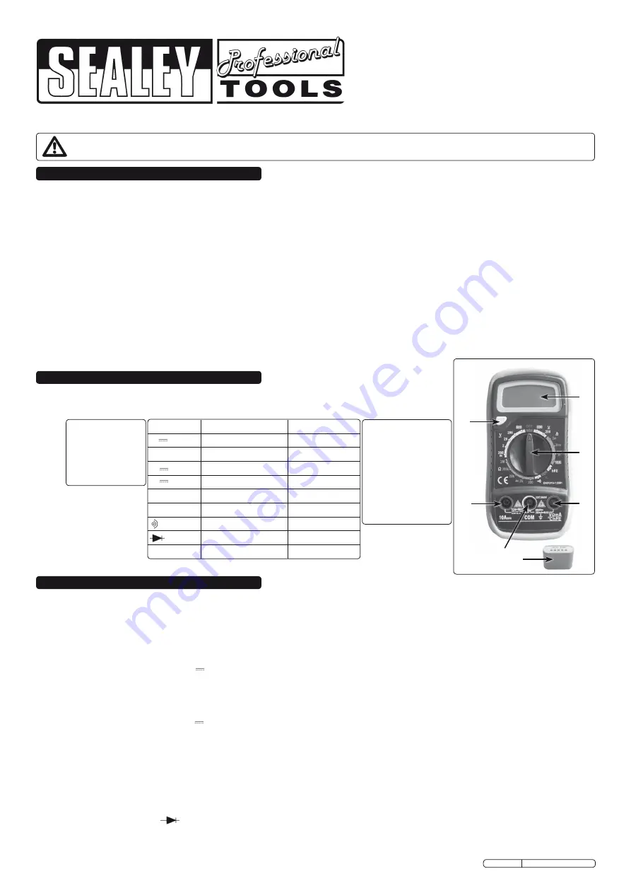
layout:
1. LCD Display
2. rotary Switch
3. V
Ω
mAºChFE Socket
4. COM Socket
5. 10A Socket
6. Hold Button
7. External Transistor
Test Plug
Measures
:
• AC and DC Voltage
• DC Current
• Resistance
• Temperature
• Diode/Transistor
Verification Mode
1
2
3
7
6
5
4
MM20.V2 Issue No: 2 - 02/07/10
function
Red lead connection Input limits
V
V
Ω
mAºChFE
600Vdc
V~
V
Ω
mAºChFE
600Vac (sine)
A
V
Ω
mAºChFE
200mA dc
A 10A
10A
10A dc
hFE
V
Ω
mAºChFE
°C
V
Ω
mAºChFE
V
Ω
mAºChFE
2k
V
Ω
mAºChFE
2k
Ω
Ω
V
Ω
mAºChFE
2M
Ω