background image

Original language version

SUPERMIG140  

MODEL No

:

SUPERMIG140   Issue No:2(L) 05/08/14

INSTRUCTIONS FOR:

SUPERMIG

       WELDER

 © Jack Sealey Limited

Summary of Contents for SUPERMIG140

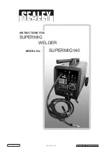
Page 1: ...Original language version SUPERMIG140 MODEL No SUPERMIG140 Issue No 2 L 05 08 14 INSTRUCTIONS FOR SUPERMIG WELDER Jack Sealey Limited ...

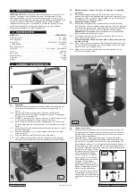
Page 2: ... dangerous and will invalidate the warranty on the welder WARNING The welder may produce voltage surges in the mains supply which can damage other sensitive equipment e g computers To prevent this happening it is recommended that the welder is connected to a power supply that does not feed any sensitive equipment INSTRUCTIONS FOR MIG WELDER 140Amp 230V MODEL No SUPERMIG140 1 2 GENERAL SAFETY DANGE...

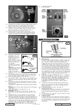
Page 3: ...k panel Place the lower end of the cylinder C Not supplied into the metal hoop E and fasten the belt around the cylinder 4 3 Connecting the gas cylinder 4 3 1 Ensure that the regulator B is closed knob turned fully clockwise and then screw it onto the cylinder finger tight only Once the regulator has opened the cylinder valve indicated by the sound of gas escaping screw it one full turn further wh...

Page 4: ... the pressure roller moulding Swing the pressure roller moulding A up and away from the drive roller 4 4 4 Straighten 40 50mm of spool wire do not allow wire to uncoil and gently push wire through the plastic guide and through the 6 or 8mm feed roller groove and into the torch liner Refer to section 7 5 on how to reverse the roller for either 6 or 8mm wire 4 4 5 Referring to fig 6 move the pressur...

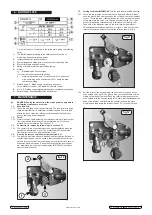
Page 5: ... the drive spindle flip it over and put it back on the drive spindle See fig 12 The groove size you require should now be visible on the face of the roller Push the roller retainer back onto the drive spindle with the opening facing left Ensure that the flanges at the base of the retainer seat fully into the circular recess in the main moulding and then rotate the retainer through 90 to lock it in...

Page 6: ...ig 14 fig 13 7 6 Replacing wire liner 7 6 1 A worn or damaged wire liner will seriously affect the performance of the welder and should be immediately replaced First wind the wire back onto the spool and secure it Remove the four screws securing the torch cable clamp to the wire feed unit fig 13 and take off the clamp Undo the torch case fig 14 and pull the wire liner from the insulation block Pul...

Page 7: ...tion 6 4 Wire deformed Check roller tension Section 3 6 Wire speed too slow Increase wire speed Section 3 7 Irregular weld head Torch incorrectly held Use correct torch angle Wire weaving in weld pool Check roller tension and adjust Section 3 6 Weld bead too narrow and raised Weld current too low Increase power and wire speed Section 3 7 Weld speed too fast Move torch slower and weave a little mor...

Page 8: ...Original language version Jack Sealey Limited SUPERMIG140 Issue No 2 L 05 08 14 ...

Reviews: