background image

Summary of Contents for 319.223560

Page 1: ...rd both the model and serial number and retain it in a safe place for future use Caution Read understand and follow ALL Instruc tions and rules for safe operation before operating this tool LT SANDER C Warranty Safety Instructions KnowYour Belt Disc Sander Operation and Maintenance Repair Parts 226560102 226560102 Sears Roebuck and Co Hoffman Estates lL 60179 U S A NRTL C LR 78936 ...

Page 2: ...and possible hazards 2_ AVOID DANGEROUS CONDITIONS DO NOT use power tools in wet or damp areas or expose them to rain DO NOT use power tools in the presence of flammable liquids or gases 4 ALWAYS keep your woik area clean uncluttered and weU lit DO NOT work on floor surfaces that are slippery from sawdust or wax KEEP VISITORS AND CHILDREN AWAY Other people should keep a safe distance from the work...

Page 3: ... affect its operation A guard or other part that is damaged should be properly repaired or replaced 20_ MAKE WORKSHOP CHILDPROOF By use of padlocks master switches or by removing starter keys_ 15 NEVER LEAVE A TOOL RUNNING UNATTENDED Turn the power switch to OFF DO NOT leave too until it has come to complete stop 16 NEVER STAND ON A TOOL Serious injury could result ff the tool tips or you accident...

Page 4: ...AND ON THE DOWNWARD SIDE of the sanding disc when using the disc sander Sanding on the upward side of the disc could cause the workpiece to fly up which could be hazardous 10 ALWAYS maintain a minimum clearance of 1 16 inch or less between tile table or backstop and the sanding belt or disc 1 1 DO NOT sand pieces of material that are too small to be safely supported 12 WHEN sanding a large workpie...

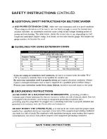
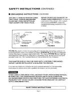
Page 5: ... W in Canada to indicate that it is acceptable for outdoor use Be sure your extension cord is properly wired and in good electrical condition Mways replace a damaged extension cord or have it repaired by a qualified person before using it Protect your extension cords from sharp objects excessive heat and damp or wet areas i GROUNDING INSTRUCTIONS IN THE EVENT OF A blALFUNCTION OR BREAKDOWN groundi...

Page 6: ...able an adapter FIGURE B can be used to temporarily connect this plug to a 2 contact ungrounded outlet The adapter FIGURE B has a rigid lug extending from it that MUST be com lected to a permanent earth ground such as a properly grounded outlet box The Canadian Electrical Code prohibits the use of adapters THE ADAPTER SHOULD ONLY BE USED UNTIL A PROPERLY GROUNDED OUTLET CAN BE INSTALLED BY A QUALI...

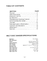
Page 7: ...Surface 11 Operation and Adjustment 12 Maintenance 15 Parts List 16 BELT DiSC SANDER SPECIFICATIONS Belt Size Disc Diameter Motor Speed R P M Net Weight Dimensions Belt Bed Tilt Disc Table Size Disc Table Tilt Bed Table Size Belt Table Tilt 4 in x 36 in 8 in 120VAC 60 Hz 6oOA 3450 R EM no load approx 43 LB approxo 17 t 2 in x 7 t 2 in x 11 in 0 o 90 10 i 2 in_x 6 1 4in 0 to450 6 Lq x 4 in 45 90 Pa...

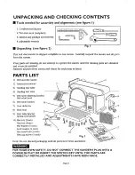
Page 8: ...e carton If any parts are missing do not attempt to operate the sander until the missing parts are obtained and correctly installed Separate all parts from carton and check for each item as listed PARTS LIST 1 Belt and disc sander 6 4 Hex head bolt 3 each Hex cap screw 3 each 10 Fig 2 Note Do not discard packaging until aU parts have been assembled FOR YOUR OVeN SAFETY DO NOT CONNECT THE SANDER S ...

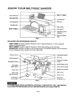
Page 9: ...ge sanding on the belt only BACKSTOP holds the workpiece when using sander in horizontal position Can be removed when sanding operation requires use of the entire belt Tension lever Tracking knob Holding bracket Belt table adjust knob Drive belt Drive belt adjusting hole 2 Hex keys 5 6 mm Fig 4 Adjusting bracket Tilt lock Backstop locking screw Bed locking screw Drive belt housing Spring load hand...

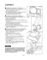
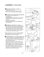
Page 10: ...sion level to tighten belt to the bed_ 7 Loosen bed locking screw lower bed to horizontal position tighten bed locking screw mi Mounting the disc sander table see figures 7 8 1 Align the bracket tO the bottom of the disc table 2_ Insert a locking washer followed by the flat washer on each screw 3 Fasten bracket with screws to table 4 Insert flat washer on disc table adjusting knob 5 install the ta...

Page 11: ...owing the dust collector to slide out of the way when not needed or when using the disc table at the end of the belt bed Note Dust deflector can not be in vertical position when using the disc table on the belt bed Dust deflector must be lowered or removed IFastening sander to work surface see figure 12 1 To mount your sander in a permanent location such as a sturdy workbench bolt the base of sand...

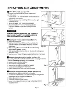
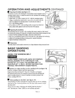
Page 12: ...mm the traddng knob counter d_ k wise a 4 ram 4_ If the sanding belt moves away from the disc turn the tracking knob cl_ V4 turn 5 Dam the switch OFT and OFF again readju_ tracldng knob ff neces _r fi Fig i 4 Im Changing the sanding belt bed position see figure I5 The sanding bed can be used in the vertical position or any angle between To use in the full vertical position do the following 1 Lower...

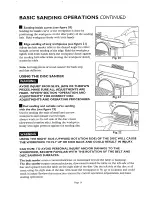
Page 13: ...backstop 3 Adjust by loosening backstop locking screw square backstop 4 11ghten backstop locking scaev_ Dust chute The dust chute can be easily connected to a large diameter shop vacuum hose BASIC SANDING OPERATIONS USING THE SANDING BELT AVOID INJURY FROM SLIPS JAMS OR THROWN PIECES SQUARE TO 90 AND ADJUST THE BACKSTOP TO CLEAR THE SANDING BELT A MAXIMUM OF Ill6 INCH REVIEW INSTRUCTION MANUAL FOR...

Page 14: ...curve sanding with the disc see figure 22 Use for sanding the ends of small and narrow workpieces and outside cur_ ed edges Always work on the teft side of the disc center downward rotation side holding the workpiece firmly with light pressure against the sanding disc Fig 22 USING THE RIGHT SIDE UPWARD ROTATION SIDE OF THE DISC WILL CAUSE THE WORKPtECE TO FLY UP OR KICK BACK AND COULD RESULT IN IN...

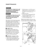
Page 15: ...ings on both ends of the idler pulley should be oiled with 3 drops of 30 weight oil after each 10 hours of operation Use a spray lubricant to ensure smooth operation on all moving table parts DRIVE BELT see figure 23 A B To adjust the drive belt t_bllow these steps 1 Remove the drive belt housing cover 2 Loosen 3 screws aUowing pulleys to slip Drive belt should be seated correctly in the motor pul...

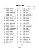
Page 16: ...re l 45 226560045 Hex nut M6 1 46 226560046 Base l 4 226560047 Screw pan hd MSx6 3 Key 48 49 5O 51 52 53 54 55 56 57 58 59 60 61 62 63 64 65 66 67 68 69 70 71 72 73 74 75 76 77 78 V9 80 8l 82 83 84 85 86 88 89 90 99 10t 101 102 Part Number 226560048 226560049 226560050 22656005 l 226560052 226560053 226560054 226560055 226560 56 226560057 226560058 226560059 226560060 22656O061 226560062 226560063...

Page 17: ...75 73 74 53 So 4g 48 g 67 26 34 33 _42 43 39 36 Page I7 ...

Page 18: ...you ca_ or visit The model munber of yotu Belt and Disc Sander will be found on the plate attached to your sander WHEN ORDERING REPAIR PARI K ALWAYS GIVE II_IE FOLLOWING INFOP_vlATION PART NUMBER PART DESCRIPTION MODEL NUMBER 31922656O NAME OF ITEM BELT DISC SAI _D ER AI1repair parts listed are available for inunediate purchase or special order when you visit your nearest Sears Service Center or t...

Reviews: