
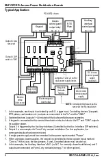
Access Power Distribution Boards
Manual
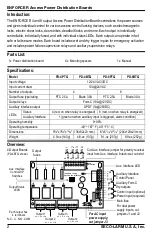
Features:
•
For 12/24 VAC/VDC operation
•
Each output individually fused
•
Each output can operate in both fail-safe
and fail-secure modes
•
Each output individually controlled
•
Individual output relays (10A@24VDC)
•
Output fuses rated at 3.0A (PTC@2.5A)
•
Individual status LEDs for each output and
for emergency input
•
Auxiliary supervision relay (1A@28VDC)
•
Equipped with dry and wet trigger inputs
(blade versions only)
•
Includes auxiliary interface to enable
emergency egress, alarm monitoring, or to
trigger other devices
•
Includes auxiliary interface disconnect,
individually selectable for each output
•
Compatible with ENFORCER Access
Control Power Supplies
Model
Output Fuse
No. of
Outputs
Main
Fuse
Type
Rating
PD-4PTQ
PTC
2.5A
4
10A
PD-4BTQ
Blade
3.0A
4
10A
PD-8PTQ
PTC
2.5A
8
10A
PD-8BTQ
Blade
3.0A
8
10A
PD-8BTQ shown


