background image


KarL4 by Garz & Fricke


Contactless Payment Terminal 


Operating Manual


Summary of Contents for Garz & Fricke KarL4

Page 1: ...KarL4 by Garz Fricke Contactless Payment Terminal Operating Manual...

Page 2: ...nts that can be damaged or destroyed by electrostatic discharge Only intervene in the unit in compliance with the relevant safety measures against electrostatic discharge ESD according to EN 100015 Pa...

Page 3: ...ntactless payment terminal 8 2 1 2 KarL4 combi terminal 8 3 About contactless Payment 11 4 KarL4 circuit board 12 5 Assembly 13 6 Keys and LEDs 16 7 Getting started 17 8 Maintenance 19 9 Service menu...

Page 4: ...e status 23 9 3 2 Provider 24 9 3 3 Field strength 24 9 3 4 IMSI 24 9 3 5 End of menu 24 9 4 1 Telemetry started 25 9 4 2 Telemetry start failed 25 9 4 3 Telemetry successful 25 9 4 4 Telemetry status...

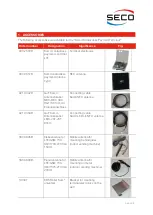
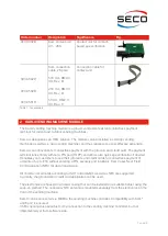
Page 5: ...l MCX MCX 090 RG174 80cm mit Erdungsanschluss Connecting cable KarL4 NFC antenna 921 0384R GuF KarL4 Antennenkabel LEDs JST JST 80cm Connecting cable KarL4 LEDs in NFC antenna 090 0995R Klebeantenne f...

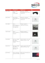
Page 6: ...schablone f r Antenne Sielaff SC Automaten Drilling template for mounting the antenna 400 2577Ra KarL4 Bohrschablone f r Antenne Drilling template for mounting the antenna 400 2843R Montage Adapter Ka...

Page 7: ...ard The payment terminal runs entirely without a PIN pad TOPP and allows also quick age verification if desired It enables your customers to use their girocards and credit cards for contactless paymen...

Page 8: ...on the front of a metal vending machine housing 2 1 2 KarL4 combi terminal The KarL4 combi terminal is the complete solution for contactless payment with the girocard as well as contactless and contac...

Page 9: ...via MDB Multi Drop Bus The KarL4 is compliant with the latest MDB specification version 4 3 from July 2019 This specification is provided by In battery mode the KarL4 activates the vending machine by...

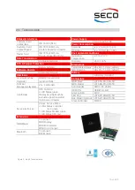
Page 10: ...hnician 2 Keys Service Menu 2 LEDs Status controller red green 1 LED Status Modem green 1 LED Status NFC red Extensions MDB Master To connect MDB Display MDB Bill Validator MDB Coin Changer Bluetooth...

Page 11: ...ss is started by placing the card or smartphone on the NFC antenna Payment is made without authorization Neither a PIN nor a signature is required The payment process is controlled by the risk managem...

Page 12: ...or chip cards one slot for the dealer card and one slot for an optional SIM card for mobile communications A SIM card is not required as the KarL4 is equipped ex works with a SIM chip which is already...

Page 13: ...ction for MDB periphery e g LCD 12 pole MODEM connection for mobile antenna 5 ASSEMBLY Installation of terminal electronics The KarL4 terminal electronics are mechanically compatible with KarL KarL Br...

Page 14: ...gth of 8 mm should generally suffice The fixing screws are not included in the scope of delivery of the NFC antenna Appropriate holes 4x 5 5 mm and 1x 25 mm must be drilled in the vending machine door...

Page 15: ...rect position of the antenna itself Contact edge for Contact edge for right edge of top edge of advertising panel decorative panel After fixing the NFC antenna with the 4 screws the connection cables...

Page 16: ...S1 and S2 keys see Figure 4 Red LED Green LED Significance Off Off Idle state terminal is switched off Off On Terminal ready for operation no errors On On Firmware signature successfully checked updat...

Page 17: ...NFC antenna Connect mobile antenna Connect contact unit Connect controller MDB Switch on vending machine Mobile connection is established if it beeps twice after switching on and the green modem statu...

Page 18: ...ition so that the KarL4 does not need unnecessary power The yellow LED must not light up Incorrect switch position Switch on right yellow LED lights up Yellow LED Debug switch Correct switch position...

Page 19: ...Functional test with test card A self test is started by inserting the test card The display shows which test is currently being carried out what the test result is Tests carried out include Triggerin...

Page 20: ...rally have the following functions S1 Access to the service menu after opening the door Calling up the next menu item within the respective menu Acceptance of a value edited with S2 In editing mode sw...

Page 21: ...s used to transmit cash register and configuration data as well as for remote maintenance through updates or configurations S1 Next menu item S2 Starts telemetry See telemetry Find updates S1 Next men...

Page 22: ...umber The vending machine number is displayed if available S1 Next menu item S2 Display if no vending machine number is available S1 Next menu item S2 9 2 5 Dealer card If a dealer card is present its...

Page 23: ...tus logged in The network technology used is also displayed Possible GSM GPRS LTE S1 Next menu item S2 Mobile status logged into foreign network roaming The network technology used is also displayed P...

Page 24: ...is displayed if available S1 Next menu item S2 Display if mobile network is missing invalid S1 Next menu item S2 9 3 4 IMSI The IMSI is shown S1 Next menu item S2 9 3 5 End of menu End of submenu S1 E...

Page 25: ...m Main menu S2 9 4 3 Telemetry successful Telemetry was carried out successfully S1 Next menu item Main menu S2 9 4 4 Telemetry status During a telemetry various screen outputs appear These are listed...

Page 26: ...nnection Presence of dealer card only if youth protection is activated by VMC Validity of dealer card Result of last day closing Result of last telemetry Outstanding transactions in the memory only if...

Page 27: ...d is inserted correctly and in the correct slot Dealer card has expired please replace it Dealer card expires in X days The last day closing was faulty Contacting the telemetry server was rejected ple...

Page 28: ...st message too short 0x1103 Type of host message wrong 0x1104 Host message answer unequal successful 0x1105 Bitmap in Host message missing 0x1200 Communication error 0x1201 No connection 0x1202 Error...

Reviews: