Q U I C K S TA R T
G U I D E
RTE 300
1 of 2
Model
14-RTE300
2
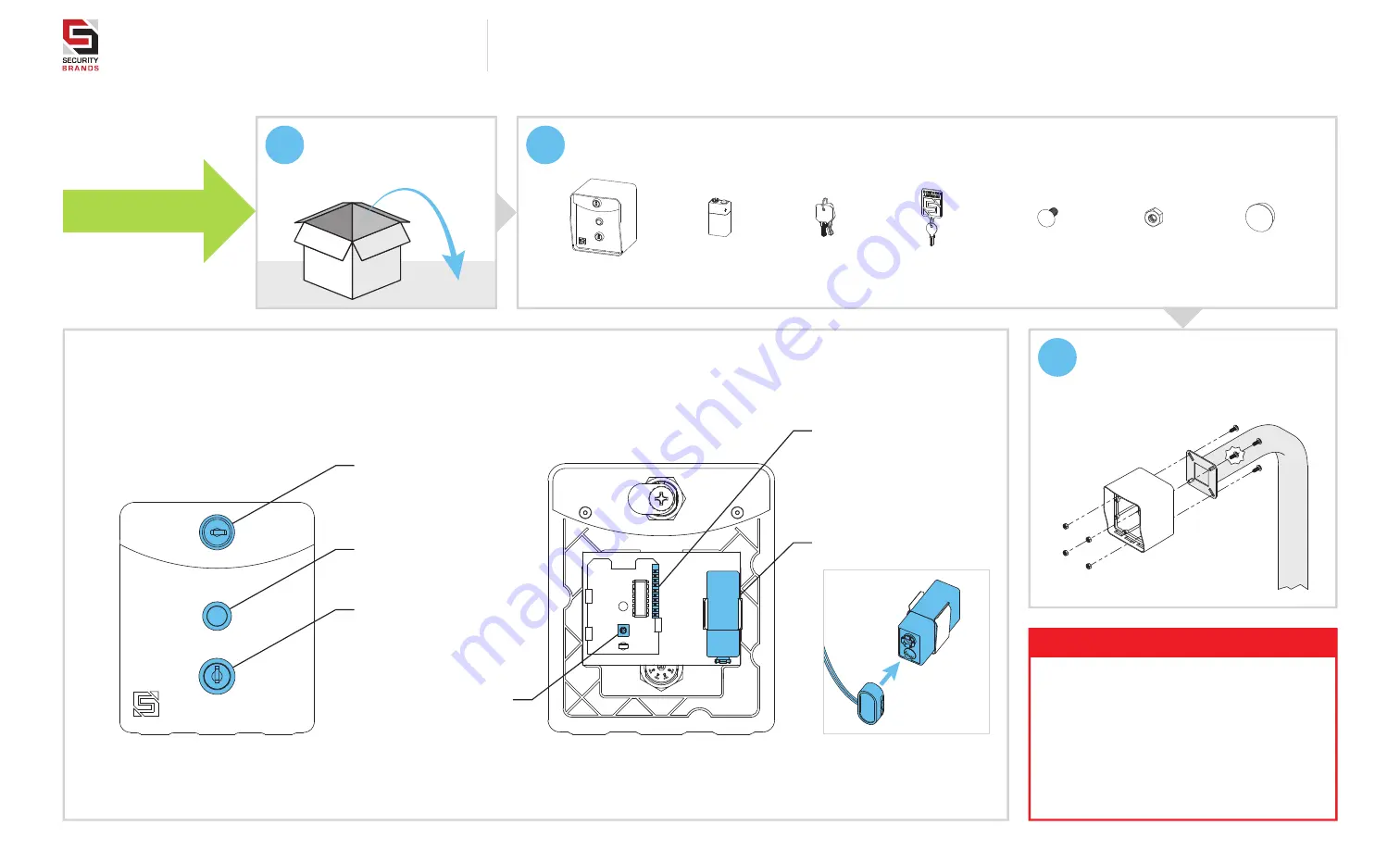
Make sure you have everything shown here.
(Screwdriver not shown)
START HERE
1
Carefully unpack box.
What’s what?
Important components labeled
RTE Unit Faceplate
(Back)
Internal wiring not shown for clarity.
9-V Battery
Must be installed before use
Key Switch
For enabling and disabling unit
(Unit is disabled as shown)
Exit Button
Triggers gate/door to open
Lock
For securing interior of RTE unit
Dip Switches
For pairing RTE unit to receiver
RTE Unit
9-V Battery
Lock Key
Carriage Bolt
( 4x )
Hex Nut
( 4x )
Hole Plug
Key Switch Keys
3
Unlock and remove faceplate
of RTE unit; then using
carriage bolts and hex nuts,
attach to pedestal as shown.
WARNING!
AUTOMATIC GATES CAN CAUSE
SERIOUS INJURY OR DEATH!
ALWAYS CHECK
that the
GATE PATH IS
CLEAR BEFORE OPERATING
!
REVERSING
or other
SAFETY DEVICES
SHOULD ALWAYS BE USED
!
RTE Unit Faceplate
(Front)
Reset Button
For performing reset procedures


