background image

Rostock MAX v2 Assembly Guide

Welcome to the Assembly Guide for the Rostock MAX v2.0 3D printer.

Version 2.53, September 28

th

, 2016

Second Edition

Copyright 2015 by Gene Buckle

Licensed as Creative Commons Attribution-ShareAlike 3.0

Questions or corrections should be emailed t

geneb@deltasoft.com

1

Summary of Contents for Rostock MAX v2

Page 1: ...embly Guide for the Rostock MAX v2 0 3D printer Version 2 53 September 28th 2016 Second Edition Copyright 2015 by Gene Buckle Licensed as Creative Commons Attribution ShareAlike 3 0 Questions or corrections should be emailed to geneb deltasoft com 1 ...

Page 2: ...ine Automatic machine can start unexpectedly Pay close attention and keep clear while power is connected to the machine The machine power supply is connected to AC voltage and can be hazardous Disconnect power before servicing this machine The hot end of the machine can reach very high temperatures of 700F and can cause serious burns The heated print surfaces heated bed can also reach temperatures...

Page 3: ...5 6 Installing the Towers Tower Wiring 79 Running Wire in the Towers 79 Setting the Towers 87 7 Assembling Installing and Wiring the Top Section 91 Prepping the Upper Tower Mounts 92 Installing the Upper Tower Mounts 93 Installing the End Stop Switches 96 Installing the Upper Tower Mounting Hardware 98 Installing the Upper Idler Bearings 99 A little prep work is in order 100 Attaching the Top Plat...

Page 4: ...Installing the LCD Panel Mount 176 Assembling the Front Panel 176 Installing the LCD Trim Panels 179 16 Installing Connecting the RAMBo Controller 182 Preparing the RAMBo Mounting Plate 182 Mounting the RAMBo Controller 184 Wire Prep End Stops 186 Wire Prep The Hot End Thermistor Connector 188 Wire Prep The Heated End Thermistor Connector 189 Wire Prep Extruder Motor Connector 190 Wiring the RAMBo...

Page 5: ...g the Z Height 238 Adjusting The End Stops 239 Verifying Extruder Stepper Operation 244 Extruder Calibration 245 20 First Print PEEK Fan Shroud 246 Configuring the Slicer 246 Printing The PEEK Fan Shroud 250 Loading Filament 251 Preparing the Heated Bed 252 Printing the PEEK Fan Shroud 253 Installing the PEEK Fan and Shroud 255 21 Second Print Layer Fan Shroud 259 Appendix A Maintenance and Troubl...

Page 6: ...atic bag it ships in until you re ready to use it The box containing the RAMBo and its wiring should also contain a printed black white sheet that looks like this http www reprap org wiki File Rambo conn all jpg Please refer to this sheet when you reach Chapter 18 This is a valuable guide to wiring the RAMBo up to your Rostock MAX Note that the connector polarity is clearly marked on the board for...

Page 7: ...t runs http minow blogspot com au for his excellent guide on calibrating delta configuration 3D printers I d also like to thank the whole gang over at the SeeMeCNC forums for providing excellent feedback This would be a much lesser creation without their contributions and insights 7 ...

Page 8: ...ion is a good choice for this and the other sizes of Allen wrenches used 5 32 Allen hex wrench 7 64 Allen hex wrench Needle nose pliers Slip joint pliers Forceps these will come in handy when routing the belts and reaching for small hard to reach parts They can be purchased from Amazon for as little as 3 50 for a set of two Wire strippers Wire cutters 5 16 open ended wrench Used primarily on the n...

Page 9: ... Harbor Freight tools for around 10 A small squeeze clamp that can open at least 6 Battery powered screwdriver If you ever needed an excuse to buy one of these THIS IS IT Pencil 40W Soldering Iron Blue thread locking compound Loctite or Permatex Threadlocker Blue A small file Elmer s Glue Stick must be marked Disappearing Purple Toothpicks Isopropyl Alcohol 12 framing square 1 Roll of ABS filament...

Page 10: ...ion You can find it here http www skygeek com wht string html While expensive you ll never really need to buy a wire tie again and it ll likely last you the rest of your life I d also recommend a little plastic box with part compartments in it They re really cheap at craft stores and are perfect for building a kit like this you can store all the various fasteners and have them ready to go as you n...

Page 11: ...anning on painting your Rostock MAX v2 especially the part edges you would be well served to carefully trace the outline of each part with a razor knife in order to cut the supporting masking tape This way you can retain the protective mask on the parts in order to make painting the edges easier Otherwise you ll have to re apply a mask to avoid getting paint on the Melamine surfaces of the parts 1...

Page 12: ...d better get on with it and get all this tape removed sigh Ok it s not THAT bad it just seems like it It beats having sticky residue all over your nice and clean Melamine parts You ll notice that there s a few strips of 2 wide masking to remove as well This tape holds the parts in the sheets so they re not damaged during shipping I recommend removing this tape FIRST Take special care when removing...

Page 13: ...uild the Rostock MAX v2 Many are in individual baggies some are in heat sealed bag packs As you go through the following Bill of Materials please count and check off each item This is important as you don t want to be short a vital part during the build It s better to find out before hand than being forced to stop the assembly process due to a missing part If you are missing any parts please conta...

Page 14: ...ck off each item as you locate it Where possible I ll include the SeeMeCNC part number enclosed in square brackets Quantities are surrounded by parentheses Hardware Package 1 Rubber foot pack Contains the following components ___ 6 10 32 5 8 Nylon Pan Head Screws 29998 ___ 6 10 32 Nylon Finish Nuts 30170 ___ 6 Injection molded feet black 17505 ___ 6 Soft rubber shoes 44010 ___ 9 10 32 3 4 Knurled ...

Page 15: ...eel Nylon Lock Nut covers all 6 32 screws 30164 ___ 14 6 32 2 Phillips Pan Head Stainless Steel screws Used for Cheapskate plates and EZStruder mount 30037 ___ 15 6 32 1 2 18 8 Stainless Steel Flathead screw Used inside of base and top side plates to retain acrylic panels and the three end stop triggering screws installed in the Cheapskate U Joint mounts 30135 ___ 25 20 1 2 Stainless Steel Button ...

Page 16: ...Used for the belt clamps 30232 ___ 14 2 56 5 8 Pan Head Phillips Machine screws Used for LCD mounting and end stop switch mounting 30650 Combined Package ___ 14 2 56 Finish Nuts Used for LCD mounting and end stop switch mounting 30642 Combined Package ___ 14 each 4 3 8 Phillips Pan Head Sheet Metal screws Used for LCD sides and tower alignment stops 30250 ___ 12 M3x 5 10mm Pan Head Machine screws ...

Page 17: ...ngs that go in the top bottom T Slot rails 30450 ___ 6 4 Stainless Steel Flat washers Used with the belt clamp screws 30449 ___ 21 608ZZ Ball Bearings Used in the Cheapskates and belt idlers 35065 ___ 1 10 32 5 8 Socket Head Cap Screw Used as a tap for the 10 32 Nylon thumb screws 29999 17 ...

Page 18: ...t idlers 68340 ___ 12 608 Cheapskate Carriage Bearing Spacers black 68326 ___ 12 608 Cheapskate Eccentric Bearing Spacers gray 68340 ___ 12 Universal Joints Injection molded Acetal 68309 ___ 6 3 1 8 Steel Universal Joint axle shafts 68325 ___ 3 1 long machined aluminum hot end platform spacers 68334 18 ...

Page 19: ...o and six are used for the belt clamps 71505 ___ 12 Small Wire Ties Used for wire management or Barbie Handcuffs Your call ___ 1 GT2 2mm pitch belt pulley pack Includes six grub screws and hex wrench 39835 ___ 3 Carriage base for U Joints 68332 ___ 1 Effector Platform 70832 ___ 6 U Joint Spring Clips 87940 19 ...

Page 20: ...Rostock MAX v2 Assembly Guide ___ 1 15 Tooth Gear Used for manually operating extruder motor 71566 ___ 6 Binder Clips Used to hold the Borosilicate glass build plate to the Onyx heated bed 58761 20 ...

Page 21: ...___ 1 USB Cable ___ 1 Onyx Heated Bed Kit ___ 1 LCD Smart Controller with SD card LCD to RAMBo Adapter Kit and 1 Soft Touch 5mm knob ___ 4 NEMA 17 Stepper Motors 4800cgm holding torque Used for three motion axes and extruder drive ___ 1 Rocker switch including spade lug crimp terminals ___ 1 25x25x10mm 12VDC fan Used to cool the PEEK section on the hot end 21 ...

Page 22: ...the hot end power and thermistor ___ 10 feet 22ga 4 conductor wire Used to extend wiring for extruder motor ___ 15 feet 26ga Black Red wire Used for hot end PEEK and part fans ___ 4 feet 3 8 diameter Expandable Mesh Wire Loom black Used to cover wiring bowden tube from the top to the hot end platform Includes 3 of 5 16 heat shrink tubing ___ 3 76 GT2 Timing Belts 22 ...

Page 23: ...Used to cover 608ZZ bearings ___ 6 Rostock MAX Delta Arms ___ 1 EZStruder Cold End Kit Includes stepper motor mounting hardware ___ 1 Hot End Kit Includes hot end heating resistors thermistor PTFE sleeve for thermistor PTC fittings and PTFE bowden tube 23 ...

Page 24: ...lic parts pack Includes LCD face LCD sides left right base and top covers Miscellaneous Parts ___ 1 300mm x 3mm Borosilicate Glass Build Plate Used with Onyx Heated Bed Yes there s a big glass disc inside that foam sleeve ___ 1 ATX Power Supply ___ 3 T Slot rail 32 long 68310 24 ...

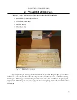
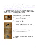
Page 25: ...Rostock MAX v2 Assembly Guide Melamine Parts Sheet 1 25 ...

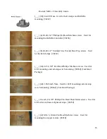
Page 26: ...Rostock MAX v2 Assembly Guide Melamine Parts Sheet 2 Melamine Parts Sheet 3 26 ...

Page 27: ...Rostock MAX v2 Assembly Guide Melamine Parts Sheet 4 27 ...

Page 28: ...t end will have to remain upright during the period that the RTV is curing The simplest way to do this is to use the large white box the Acrylic parts are shipped in Take the parts out of the box and using a pair of scissors cut a hole in the top by shoving the scissor blade straight in Put the Acrylic parts back in the box and set it aside we ll use it soon Before we start on this I d like tighte...

Page 29: ... s PTFE tubing You ll start by coating each heating resistor with RTV as shown in Fig 3 3 You ll want to try to keep the resistor leads free of RTV but don t skimp on the RTV application You can always clean off excess RTV after it s cured This stuff is goopy and sticks to everything Keep a paper towel or ten handy 29 Fig 3 2 RTV heating resistor Fig 3 3 Coating the heating resistor with RTV ...

Page 30: ... in You don t want any air pockets in there Air pockets can shorten the life of the resistors because air exposure will allow the resistor to over heat in a single area Don t be surprised if your application of RTV is not nearly as neat as shown above These hot end assembly photos were shot by Andy Oprisko a SeeMeCNC employee He s literally built hundreds of hot ends and is very very good at it 30...

Page 31: ...Of Shielding and slide the a PTFE tube on to each of the thermistor leads as shown below Using a pair of needle nosed pliers bend a 90 degree angle in the thermistor and PTFE tubing as shown below Take special care to not damage the thermistor head It s made of glass and is very delicate Take the nozzle off the Permatex Ultra Copper RTV tube and dip the end of the thermistor into the RTV as shown ...

Page 32: ...istor should now be installed in the thermistor port on the flatted side of the hot end as shown Set it aside in a safe place to allow the RTV to cure 32 Fig 3 9 Thermistor installed Fig 3 10 Hot end plugged into the cardboard box for curing ...

Page 33: ...e However if you use FOUR hoses you can deliver four times the volume In our case volume is amperes the water pressure is volts So using four wires gives us four times the amps that a single wire can deliver Understand that if you try to draw too much through a single wire the electrons inside the wire basically get into a fight with each other all trying to escape through the same tiny hole at on...

Page 34: ...I m just a bit driven about what my wiring looks like The simplest way to get the four wire pairs needed for the heated bed is to grab a connector that s already got them grouped for us Look through the wiring bundle until you find a connector bundle that looks like what is shown in Fig 3 15A It may also be split apart and look like what s in Fig 3 15B You may be tempted to tin the bare leads of t...

Page 35: ...ext The important parts are the yellow and black wires It doesn t really matter WHERE you get them so long as the wires you choose are long enough to do the job How long is long enough Well grab the bundle with the 8 pin connector on that and use that as the base length If you don t have the 8 pin connector find the longest yellow black wire set on the power supply match to the next longest etc Do...

Page 36: ...se four free leave the other two in place It saves you the trouble of having to cover them with electrician s or Kapton tape to prevent them from shorting in the case of the yellow wire Like you did with the four heater bed pairs bundle them up or simply set them aside 36 Fig 3 18 Cut free Fig 3 19 Wires ready to use ...

Page 37: ...wire tie you ll need to supply this bundle up the unused wiring and then use another to bind the bundle to the power supply as shown below Now you ll need to locate the RAMBo power connector this is a six position compression terminal block and will be found in the little zip lock baggie that s in the RAMBo box 37 Fig 3 20 Routing the wire tie through a vent Fig 3 21 All done Fig 3 22 RAMBo power ...

Page 38: ... could be shipped with them opened but you should check by trying to loosen the screw in each one If it clicks softly as you loosen the screw it s fully opened Make sure they re tight after inserting the wires Make sure that there s no stray strands escaping the terminal position for either bundle A single strand could short the power supply and cause you no end of grief Grab the last two pair of ...

Page 39: ...ir wire bundles together it will help act as a strain relief for the four pair going into the compression terminal block and it looks pretty neat too The final task in this chapter is add the spade lug connectors to the power on wiring Strip off about 3 8 of insulation from the black green wires that you cut from the big ATX connector and crimp the spade lug connector to each as shown in Fig 3 30 ...

Page 40: ...ostock MAX v2 Assembly Guide Set the power supply aside and we ll begin the main construction process 4 Building the Base For the following task you ll need the following parts 40 Foot Pack Power Supply ...

Page 41: ...make sure that we install the feet on the right side of the plate If we don t they ll be facing up and won t be much good for holding the machine off the table The top surface is easily identified Lay the Base Bottom Plate flat with the large square opening facing you When the plate has the right face up the two notches below the rectangle will be on the left and the single notch will be on the ri...

Page 42: ...ed The 1 2 screws are used to retain the Acrylic side panels that we ll be installing toward the end of the build Let s get those installed first Each of the three vertical supports should have one 1 2 flat head screw installed in each end as shown on the left You don t want to install the screw all the way just drive it enough so that the bottom face of the screw is flush with the opposite face o...

Page 43: ... are two holes on each end of the vertical supports that can take the retaining screws we re cutting threads for The holes you need to use are the top ones Write top on each vertical support plate in the location shown in the figure below and then carefully drive the 10 32 socket head cap screw through the hole closest to the top Drive the screw though completely and then remove it Repeat this for...

Page 44: ...Rostock MAX v2 Assembly Guide 44 Fig 4 10 Marking the top of the part Fig 4 11 Drive the screw all the way through ...

Page 45: ...ser cut pocket The laser cut pockets are designed to be a very snug fit However sometimes the pockets may feel a bit too tight If this is the case try inserting the nut in from the other face It may be easier due to the slight bevel the cut has in it due to the laser focus You may also run into a situation where the nut pocket doesn t hold the nut tightly enough to keep it from falling out In that...

Page 46: ...ide When you re done with one of the vertical supports you should have four nuts installed as shown Go ahead and install the eight remaining nuts in the two vertical supports 46 Fig 4 13 All four nuts installed Fig 4 14 All done ...

Page 47: ...that it only fits one way shown above and it s a pretty easy install The method I ve found that works the easiest is to pin the power supply between my knees while I install the mount To attach the power supply mount all you need to do is thread the nylon screws in with your fingers and then lightly tighten with a flat bladed screwdriver Take care to not over tighten the screws 47 Fig 4 15 Power s...

Page 48: ...ime the fit tolerance is loose enough that they just drop in Make sure that when you re installing the vertical supports that the 1 2 screws you installed are facing inward These screws are used to capture the acrylic covers that are installed later 48 Fig 4 18 Vertical support power supply installation Fig 4 19 Right side view of the installation Fig 4 20 Right side fully seated ...

Page 49: ...tical supports to the bottom Leave them just a little bit loose for now Leaving them a bit loose will make installing the top a lot easier when we reach that point Before you can install the last of the three vertical supports you ll need to install the two 49 Fig 4 21 Both sides seated Fig 4 22 Example of an installed screw ...

Page 50: ...er the top of them Use two 6 32 1 Stainless Steel pan head screws to attach the front vertical support over the two RAMBo legs as shown below Like the two back supports leave this a bit loose in order to assist with fitting the top Checkpoint Video 1 http youtu be Bdv5sja3EQk 50 Fig 4 23 Support Legs Fig 4 24 Support legs installed Fig 4 25 Front vertical support installed ...

Page 51: ...flat This ensures that a properly tightened drive gear won t be able to rotate on the shaft when properly tightened Thread one of the grub screws into a pulley and slide the pulley on to the stepper shaft as shown Make sure that the grub screw is aligned with the flatted portion of the shaft You also want to make sure that the tip of the stepper shaft is flush with the outside face of the pulley a...

Page 52: ... it but it ll work just fine You ll want to use the included Allen wrench to tighten down the grub screw Wipe off any excess thread locking compound after the screw is tightened down Install the second grub screw using the same process you followed for the first 52 Fig 4 27 Pulley grub screw aligned Fig 4 28 MOAR THRED COMPOUND ...

Page 53: ...Rostock MAX v2 Assembly Guide Now install the drive pulleys on the other two stepper motors the same you did with this one 53 Fig 4 29 Properly installed pulley ...

Page 54: ...Rostock MAX v2 Assembly Guide Assembling the Tower Supports For this task you ll need the following components 54 3 Stepper with Drive Gears ...

Page 55: ...t bearings by sandwiching each 608ZZ bearing between a pair of the black idler bearing spacers The idlers are very simple to assemble Go ahead and assemble the other five bearings and set them aside 55 Fig 4 30 Idler bearing components Fig 4 31 First one side Fig 4 32 and then the other ...

Page 56: ...u ll slide the tower down until the bottom strikes the head of the screw This will guarantee that you ve got all three towers at the same height You may notice there s a bit of Scotch tape on the left most mount This was done because the laser cut pocket was just a bit loose and I needed to be able to hold the nut in place until there was a screw in it Note that the two mounts on the right are mir...

Page 57: ...and install it using four of the M3x10mm screws Apply a little bit of thread locker to each one before installing Assemble the next stepper motor mount the same as you did the first one but assemble the third one mirrored When you re done the three mounts should look like the figure below 57 Fig 4 34 Mounting plate alignment Fig 4 35 Screws installed Fig 3 36 Correct assembled stepper motor mounts...

Page 58: ... holds the idler bearing assemblies that you put together In order to install them you ll need to add a 6 32 washer to two of the 6 32 1 3 4 Stainless Steel flat head screws and insert them into the back of each stepper motor mounting plate as shown below 58 Fig 4 37 Tower supports ready to go Fig 4 38 Idler bearing support screws ...

Page 59: ... 32 flat washers and two 6 32 Nylon lock nuts and tighten them finger tight The looseness will help install it in the bottom plate and assist in fitting the top plate Repeat this process for the other two assemblies Checkpoint Video 2 http youtu be vckZcN8XmQc 59 Fig 4 39 Idler bearings installed Fig 4 40 Tower support installed Fig 4 41 X and Y axis motors ...

Page 60: ...ies attached to the base of the machine Drop the X and Y axes in as shown below Install two 6 32 1 pan head screws into each one just a bit more than finger tight We want a bit of wobble to help with the installation of the top 60 Fig 4 42 X and Y axis tower motor supports in place ...

Page 61: ...w The connector is a tight squeeze but it WILL fit Now you need to install four of the 20 cap head screws and four T Slot nut plates into each tower support assembly Only thread the T Slot nut plates enough to feel the end of the screw catch all the threads in the plate the space is needed in order to properly fit inside the slot in the tower 61 Fig 4 43 Routing the Z axis stepper wires Fig 4 44 T...

Page 62: ...outu be HgluRmxKL5Y Installing the Base Top Plate The next task requires the following components The six t nuts specified above should come from the Onyx Heated Bed package and not from the t nuts included in the hardware pack 62 Fig 4 46 All four in place ...

Page 63: ...t will penetrate into the Melamine when pressed in with enough force I d recommend using a hammer a single sharp tap should be enough to set the t nut flush with the Melamine surface After the t nut is in place cover it with a short length of Scotch or masking tape to hold it in place You don t want them to pop out on you when you re installing the Onyx 63 Fig 4 47 Onyx Heated Bed hardware pack Fi...

Page 64: ...ping out while you re working your way around the top It takes a little patience to get done but it s vastly easier than installing the original Rostock MAX top plate Once you ve gotten the top fully seated fully tighten all of the 6 32 1 screws Tighten the three vertical supports both top and bottom and then tighten down the three tower supports Also tighten the screws holding the two idler beari...

Page 65: ...ideo 4 http youtu be j2ee qap4Kw 5 Installing the Onyx Heated Bed Installing the Thermistor Power LED and Power Wires For this task you ll need the following components from the Onyx Heated Bed package 65 Fig 4 51 Completed Rostock MAX v2 Base ...

Page 66: ...ill protect the top of the thermistor as well as prevent RTV from leaking on the top of the board Leave a little bit of the Kapton folded over You ll be removing the tape once the RTV has cured Once you ve got the Kapton applied open up the small package that contains the thermistor and the PTFE tubing Cut two 3 8 long bits from the PTFE tubing and slide them on to the thermistor leads You ll then...

Page 67: ...thermistor end in and out of the hole a few times this will help to eliminate any bubbles that formed when it was inserted into the hole the first time Cover the end of the thermistor with Kapton tape as shown below This will both protect the thermistor and help you position the leads for the next step soldering them in 67 Fig 5 2 PTFE insulators installed Fig 5 3 90 degree bend Fig 5 4 Thermistor...

Page 68: ...lip off the excess leads Note that we re using the pair of pads closest to the thermistor The more distant pair is where we ll install the thermistor signal wires We re going to install the power LED next The LED has polarity to it so we need to make sure that it s installed correctly otherwise they won t light up 68 Fig 5 6 Thermistor taped into place Fig 5 7 Soldered down Fig 5 8 and trimmed ...

Page 69: ...a flatted outline that matches that of the LED base Bend the leads over so they are laying flat against the two solder pads as shown below and then solder them into place If you hold the rim of the LED in place with your thumbnail while you bend the leads over you ll end up with a nice ramp to the leads as shown in Fig 5 10 69 Fig 5 9 LED orientation Fig 5 10 LED ready to solder in Fig 5 11 Leads ...

Page 70: ... Onyx The LED needs to be pushed in so it s flush or slightly below the top surface of the Onyx as shown below The next step is to install the resistor that the Onyx power LED needs to operate Take one of the resistors from the package and bend the leads as shown in Fig 5 14 70 Fig 5 13 Correct LED depth Fig 5 12 and trimmed ...

Page 71: ...in the wiring pack and cut a section 17 long from it The 18ga wire is easy to identify it s got 18 AWG printed in a repeating pattern all along the outer jacket Strip the gray insulation off the four wires You can discard the single bare wire and the thin 71 Fig 5 14 Properly bent leads Fig 5 15 Ready for soldering Fig 5 16 Soldered and ready to trim Fig 5 17 Identifying the 18ga wire ...

Page 72: ... middle of the square pad with the symbol next to it The indicates that this is the Positive connection You may need to use something to hold the wire into place while you solder it I used a pair of wire cutters to weight it down Now perform the same task with the black wire The black wire will be soldered to the pad marked with the symbol The symbol indicates that this is the Negative or Ground c...

Page 73: ...Return the other one to the wiring bag Strip about 1 8 of the insulation of the bare ends of the thermistor wires and solder them on top of the solder pads that are aligned with the two solder pads you soldered the thermistor to One wire per pad and take care to avoid solder bridges Make sure there s no blob of solder bridging the two pads or the thermistor won t operate 73 Fig 5 21 Thermistor wir...

Page 74: ...sh off the wiring is to cover all the exposed connections with Kapton tape This will help insure against any accidental shorts The tape will also act as a bit of strain relief for the wiring 74 Fig 5 25 Main bed connections covered Fig 5 26 LED covered ...

Page 75: ... the Onyx on the base you ll need to route the power and thermistor signal wires through the center of the snowflake mounting plate and the base as shown below Pull the wiring forward through the opening in the front facing vertical support in order to get them out of your way 75 Completed Onyx Fig 5 27 Wires routed through the center hole ...

Page 76: ...tly opposite the Z tower in the rear Now it s time to attach the Onyx and its mounting plate to the base grab the round nylon spacers and the six 4 40 flat head screws that were included with the Onyx Turn the Onyx so that the first hole lines up with the first hole in the mounting plate The first hole is the one between the two LED clearance notches Slide a 4 40 screw through the Onyx mount and s...

Page 77: ... screw will go through the 1 mounting hole as shown below Tighten the screw a small amount A half or three quarter turn should do it We just want it to grab enough threads to keep it from popping out while we line up the other five screws 77 Fig 5 31 First screw in ...

Page 78: ... hole in the base Tighten the six screws using the order shown in Fig 5 32 above This will help ensure that the Onyx remains as flat as possible when it heats As you tighten each screw make sure you only turn it a bit more than finger tight if you apply too much force the screw head will damage the Onyx Checkpoint Video 5 http youtu be x_KUriGPn_4 78 Fig 5 32 Screw fastening order ...

Page 79: ...the tower you ll need to cut the red black wires in half so you have two red black pair of equal length In the Rostock MAX v2 you ll be routing the hot end extruder stepper and end stop wiring through the center of the three towers If you re upgrading a Rostock MAX v1 and using the original towers please make sure to gently file off any sharp edges on either end of each tower In order to do this y...

Page 80: ...g around your fingers to get a good grip on it and holding the exposed wires in one hand pull the Nylon string away from you along the length of the cable Continue doing this until it s split the whole gray outer jacket When you re done you can discard the outer jacket and the thin aluminum wrap However don t discard the bare wire that was woven around the four conductors You re going to use that ...

Page 81: ...e wire counter clockwise will help this process along When you re done it should look like the image shown below Because the 18ga wire is pretty stiff you should be able to run it inside the tower pretty easily Just do it an inch at a time to take advantage of the greater stiffness afforded over a shorter length of wire If you re unable to do it you can skip ahead to the next page and see how the ...

Page 82: ... stop wires Carefully stretch out the three wire pairs included in the bundle and spindle the ends together as shown in Fig 6 4 Now thread the bare wire you recovered from the 18ga 4 conductor cable through the center of the next tower When you ve pulled it all but about four inches wrap the wire around the spindled end of the end stop wires as shown below 82 Fig 6 4 End Stop wires bundled togethe...

Page 83: ... MAX v2 Assembly Guide Now carefully stuff the wires into the center opening in the tower while gently pulling on the bare wire coming out the other end of the tower 83 Fig 6 6 Getting it started Fig 6 7 Done ...

Page 84: ... to you should feel yourself pulling the wire from either end Once you ve identified your first black white pair write an X on the spade connector using a Sharpie or other indelible marker At the opposite end twist the wires together about 1 4 from the end of the crimp on connector and label it When you ve got both ends marked tie a very loose knot in the top pair as shown to the right Repeat this...

Page 85: ...eviously Spindle them together with the four conductor 22ga wire as tightly as you can Thread the bare wire through the last tower like you did previously and wrap the end around the spindled portion of the 24ga 26ga wires Just as you did with the end stop wires carefully feed the wire bundle into the center hole and as you gently pull on the end of the fish wire 85 Fig 6 10 Identifying the 22ga 4...

Page 86: ...uted along with the other wires Use the same method as used on the end stops and tie a knot in one pair of black red wires at both ends This knotted pair will be used for the PEEK section fan the un knotted pair will be used for the layer fan 86 Fig 6 12 Success Fig 6 13 PEEK fan wires knotted ...

Page 87: ...in its respective tower support assembly We re going to start with the Z axis In order to set the Z axis tower the one with the 18ga wires you ll need to turn the T Slot nut plates such that they re oriented vertically as shown below 87 Fig 6 14 T Slot nut orientation on the Z axis ...

Page 88: ...the tower down make sure that the T Slot nut plates are sliding into the t slots on both sides of the tower You ll want to drive it down until it comes into contact with the 4 leveling screw that you installed in the tower assembly After the tower is set use a 5 32 Allen hex wrench to slightly tighten the 20 cap screws finger tight You ll tighten them up after the top as been mounted Once the towe...

Page 89: ...e on the right of the tower as shown below The X and Y towers are set in a similar fashion The end stop wires in the X axis tower also route through the right side rounded slot as shown 89 Fig 6 18 Routing the Z axis wires forward Fig 6 19 X axis wire route Fig 6 20 X axis tower set in place ...

Page 90: ...embly Guide Now you can set the Y axis tower in to place Unlike the Z and X axes tower wiring the Y axis tower wires exit to the left as shown Checkpoint Video 6 http youtu be qbtiOqR6aZQ 90 Fig 6 21 Y axis wiring route ...

Page 91: ...s doesn t affect the operation of the printer at all it just looks silly In order to make sure you don t make the mistake take a look a the image below You ll want to orient the top section base plate as you see above This will help ensure that YOU don t build yours backwards like I did I ve revised many of the original images that show the reverse orientation but not all of them As long as you fo...

Page 92: ... mounts three tower depth stop screws need to be installed as shown below These screws perform the same function as the ones previously installed in the lower tower mounts This helps guarantee that the top section will be at the correct height on all three towers 92 Fig 7 1 Depth stop screws installed ...

Page 93: ...ur left has a tower depth stop screw installed and set them into the tower socket as shown in Fig 7 2 Once you ve gotten them staged as shown carefully rotate them counter clockwise until both parts are in the position shown in Fig 7 3 Now rotate the left mount until it s firmly against the side of the notch as shown in Fig 7 4 93 Fig 7 2 Staging the tower mounts Fig 7 3 Rotating the mount pair Fi...

Page 94: ...n the position shown in Fig 7 5 Rotate the mount clockwise until the right face of the mount is flush with the right side of the notch Repeat this process for the remaining two tower locations 94 Fig 7 5 Right mount rotated Fig 7 6 Mounts in place Fig 7 7 Note location of the depth stop screw ...

Page 95: ...t you spread the mount apart at the very ends to get the first tab of the spreader block set It WILL fit but be careful you don t want to break the tower mounts Repeat the process for all three upper tower supports 95 Fig 7 8 First tab inserted Fig 7 9 Second tab set in place Fig 7 10 Spreader fully seated Fig 7 11 Completed support installation ...

Page 96: ... right side of the over turned tower mount as shown in Fig 7 12 Next you ll slide the end stop switch over the two screws Make sure you ve got the switch properly oriented The back of the switch should be closest to you as shown Finally install one 2 56 finish nut on to each mounting screw Take special care to not over tighten the screws or you ll crack the switch body which could cause it to malf...

Page 97: ...Rostock MAX v2 Assembly Guide When you re finished the underside of the top plate should look like Fig 7 13 below 97 Fig 7 16 Assembled top plate ...

Page 98: ...owing components Install four 20 button head screws and four T Slot nut plates into each upper tower support as shown in Fig 7 17 Thread the nut plates only a couple of turns they need to be as loose as the lower ones were in order to properly fit the towers 98 Fig 7 17 Hardware installed Fig 7 18 Offset view ...

Page 99: ...d the following components First you ll need to put together two idle bearing spacers with one bearing This is the same task you did for the lower idler bearings Now install the assembled idler using a 1 75 pan head screw as shown below 99 Fig 7 19 Upper idler bearing Fig 7 20 Screw inserted ...

Page 100: ...step to do first You ll notice that each of the upper support spacers has a hole in the center This hole needs to be tapped in order to attach the top cover at the end of the build Since we ve got the top plate on the table it ll be easy to do this task You re going to need the 10 32 Socket Head Cap Screw to use as a tap Use a 5 32 Allen wrench to drive the screw in Take care to make sure that the...

Page 101: ...Rotate the top plate to match as shown below In order to give yourself room to route the wires through the tower openings in the top plate you ll want to rest the plate on top of the towers We ll start the installation with the X axis and the end stop wires Carefully route the end stop wires through the opening under the idler bearing as shown on the right Once you ve got them run move on to the Y...

Page 102: ...r motor wires up through the hole just as you did for the end stop wires Since the wire gauge is very similar between the stepper wires and the fan wires knot the fan wires loosely before routing them It ll help you identify them later Finally route the Z axis wires as shown on the right Checkpoint Video 8 http youtu be IIHX8W3uYdU 102 Fig 7 25 Fan wires Fig 7 26 Y axis wires routed Fig 7 27 Z Axi...

Page 103: ...e it above The idea here is to prevent the top from settling too much on one axis until you get the others set to the same depth If one or more axis settles completely there will be too much of an angle to allow the other axes to slide onto the towers easily Once you ve got all three towers started go back to the Z axis and get the upper set of t slot nuts started in the tower as shown in Fig 7 29...

Page 104: ...th the small stop screw on the left side of each tower mount Tighten each of the tower s button head cap screws only finger tight We ll come back and tighten them the rest of the way once the end stops are connected and the other wires are routed tied down Checkpoint Video 9 http youtu be QrD9aWm9ykU 104 Fig 7 31 Fully seated ...

Page 105: ...e X tower You may need to lift the X tower a little bit to lessen the bend radius the wire needs to feed Now carefully seat each spade lug connector on to the end stop switch as shown below It doesn t matter where the white black wires go just as long as one is on the innermost spade lug and the other the outermost Repeat this process for the X and Y towers Once all three towers are done carefully...

Page 106: ...plate is flipped in the photo but the wire path remains the same The figure above shows the Y and Z end stop switch wire paths The start point for both is the X axis on the lower left 106 Fig 7 35 Z and Y axis end stop switch wire paths ...

Page 107: ... four 18ga wires from the Z tower and the four 26ga wires from the Y tower through the center hole in the top plate Carefully feed 30 of wire as measured from the top plate This will give you plenty of length to work with when it comes time to wire up the hot end 107 Fig 7 36 Routing the hot end wires Fig 7 36A Wires pulled ...

Page 108: ... center hole That will give you about 8 of wire from where the wires exit the top of the Y tower to the center of the top plate Use a bit of Scotch tape to hold the wires in place If you fold over the end of the tape it ll give you a nice handle to pull on when it s time to remove it 108 Fig 7 37 Extruder drive wires ...

Page 109: ...to work Let s start with the X axis Make sure that the end stop wires exit the top of the tower to the right when the wires are pulled tight using the wire tie it will keep them from interfering with the belt path When you re done re install the idler pulley if you removed it and we ll move on to tying down the end stop wires between the X and Z towers 109 Fig 7 38 Example tie down point Fig 7 39 ...

Page 110: ... and Z towers These two points are used to retain the end stop wires that go from the X to the Z tower Insert a wire tie from below as shown below and pull it tight and clip off the tail of the wire tie 110 Fig 7 43 X Z path tie down points Fig 7 44 Tie ready to fix in place Fig 7 45 Tightened clipped ...

Page 111: ...r wire tie in the other location and we ll move on to the Z axis Once the Z axis wires are tied out move on to the Y axis and tie those down as well 111 Fig 7 46 Tying down the hot end wires Fig 7 47 Tied in place Fig 7 48 Y axis wiring tied down ...

Page 112: ... the Y axis is done tie down the end stop wires that run from the X to the Y axis as shown below The process is the same as what you did for the X Z end stop wires Checkpoint Video 10 http youtu be VhYcsn17Ru4 112 Fig 7 49 X Y tie downs ...

Page 113: ...ires under the feet etc The first thing to remember about this process is to make sure that the tower is in contact with the depth stop screw BEFORE you begin to tighten down each tower bottom top If you don t the top of the machine won t be level and that will make calibrating the printer very very difficult Grab your trusty 12 framing square and a clamp and set them up as shown below I started o...

Page 114: ...e long arm of the square to contact the bed all the way across You ll need to offset the angle of the square a bit to keep it off the Kapton tape in the center Once you ve got it square tighten the screws using a 5 32 Allen wrench using the pattern shown below 114 Fig 7 51 Tightening order Fig 7 52 Tightening screw 1 ...

Page 115: ...er move up to the top and tighten those four using the same order as you did the bottom Make sure the top of the tower is in contact with the stop screw Repeat the square tighten tasks for the Z and Y towers Checkpoint Video 11 http youtu be HWNhClZoRFU 115 Fig 7 53 Tightening the top screw 3 ...

Page 116: ...on the sleeves are VERY tight They may also have a sharp lip on the outer face You might want to use some of the scrap Melamine to help you press the sleeves on to the bearings without leaving a ring on your palm Start by laying a sleeve half on the table open face up Set a 608ZZ bearing into it and firmly press into place You can use a bit of Melamine scrap as I suggested previously or the back e...

Page 117: ... the table with the same orientation as before Lay the bearing into it and press into place Repeat this process for the remaining 11 608ZZ bearings 117 Fig 8 3 Ready to press home Fig 8 4 Assembled bearing Fig 8 5 Finished bearing set ...

Page 118: ...t pins into the holes indicated by the arrows in Fig 8 6 IMPORTANT Note the orientation of the inner plate above The pair of holes on the left are closer together than the pair on the right You must retain this orientation otherwise the Cheapskate outer plate won t fit in it s correct orientation eyes looking right when it s time to assemble the Cheapskates 118 Fig 8 6 U Joint carriage installatio...

Page 119: ... you find that happening just remove that alignment pin and hold it in place until you can get the socket head cap screws installed From the front side of the U Joint carriage insert two 6 32 5 8 socket head cap screws through the holes indicated Install two 6 32 Nylon lock nuts on the back and tighten them down using a 7 64 hex wrench and a 5 16 wrench 119 Fig 8 7 U Joint carriage fitted properly...

Page 120: ...install the screw try to leave the bottom of the head even with the top of the inside carriage plate as indicated by the green line in the photo This will give you a consistent start point when it comes time to calibrate the printer when your build is completed Make sure you install each screw the same way on all three Cheapskates This will help give you a consistent starting point when you being ...

Page 121: ...erfectly straight and are free of any scarring If the axle is bent or badly scarred contact support seemecnc com for a replacement The U Joint carriage has a shallow slot to hold the u joint axle Press the axle into the slot Make sure that the axle is perfectly centered on the u joint carriage 121 Fig 8 13 Axle pressed into position Fig 8 14 A properly centered axle ...

Page 122: ... Repeat this task for all three u joint carriages Installing the Belt Clip T Nuts For this task you ll need the following components Install two 4 40 T Nuts in the back of all three Cheapskate inner carriage plates as shown Make sure the barbs on the t nuts are fully seated in to the Melamine A good tap with a hammer should fully set them Cover each one with a bit of Scotch tape to hold them in pl...

Page 123: ...c spacers and two roller bearings with Eccentric spacers The eccentric spacers are used to correctly adjust the grip that the roller bearings have on the towers The eccentric spacers have a small bulge on one face When inserting the spacers into the roller bearing make sure the bulges are lined up with one another as shown above in Fig 8 18 123 Fig 8 17 Standard spacers Fig 8 18 Eccentric spacers ...

Page 124: ...Now slide on two roller bearings equipped with the standard spacers as shown below Now install the roller bearings equipped with the eccentric spacers You ll note that the bulges on the two eccentrics are aligned This is very important If they re not lined up you ll have problems getting the Cheapskates adjusted properly 124 Fig 8 19 Outer plate ready for bearings Fig 8 20 Standard bearings added ...

Page 125: ...mes time to adjust them Now you can slide the inner plate on to the four screws as shown Fix the outer plate into place with four 6 32 nylon lock nuts as shown below Fully tighten each one Repeat this process for the Y and Z towers and then we ll move on to adjusting the proper grip for each Cheapskate 125 Fig 8 22 Cheapskate resting on the X tower Fig 8 23 Inner plate installation Fig 8 24 Inner ...

Page 126: ...the same grip as you can get it A good way to estimate that is to make sure that the little bulges on the eccentric spacers match across all three Cheapskates Get one set as good as you can and then make the position of the others match If it doesn t get you dead on it won t take much adjustment after that point The checkpoint video below illustrates how a properly adjusted Cheapskate should move ...

Page 127: ...m the parts list required the same job is done with fewer parts making for a much simpler installation Tip if you lay the machine down it s easier to route install the belts Belt Routing Take one of the GT2 drive belts and thread it into the notch at the base of the Z tower as shown in Fig 9 1 The belt shown below is slightly twisted but please make sure that the belt teeth face in towards the tow...

Page 128: ...er the upper idler and around the top of the GT2 drive gear as shown in Fig 9 2 Pass the belt around the gear and under the lower idler as shown below 128 Fig 9 2 Passing under the idler and over the gear Fig 9 3 Around the gear and under the idler to Grandmother s house we go ...

Page 129: ...d the tower as shown below Now you can pull the belt up towards the top and route it between the tower and the top plate opening as shown Now route the belt over the top of the idler and back down through the tower opening as shown 129 Fig 9 4 On our way to the top Fig 9 5 Belt under the Cheapskate Fig 9 6 Belt at the top Fig 9 7 On the way back down ...

Page 130: ...ers or forceps grab the belt tip and pull it through You can slide the belt end up behind the U Joint carriage to keep it out of the way while you feed the other end of the belt up from the bottom At this point inspect the belt path to ensure that the belt is not rubbing against any of the wiring Install the belts for the Y and Z towers at this time You may want to tape the ends in place until you...

Page 131: ...ut belt clamp and install it into the notch capturing only the top end of the belt Holding that end of the clamp in place pull the bottom end of the belt tight and then press the belt clip in place You want to pull the belt tight enough that little if any tension adjustment will be required at the top idler pulley If you re not feeling especially dexterous today tape the ends of the belt clamp in ...

Page 132: ...t clamp Now insert a 4 40 1 2 socket head cap screw through the washer plastic bearing and then tighten with a 3 32 Allen wrench Install the other plastic bearing washer screw on the opposite side as shown to the right 132 Fig 9 11 Plastic roller bearing and 4 washer in place Fig 9 12 Screw installed Fig 9 13 Belt clamp locked in place ...

Page 133: ...ou chose to tweak the belt tension at that point instead of on the top idlers Adjusting the Belt Tension The mounting for the top idler pulleys is designed to allow you to increase the tension on the belts if necessary Setting proper belt tension is more magic than science at this point but the following instructions will get you at a pretty good default tension Insert a P1 screwdriver diagonally ...

Page 134: ... to the idler pulley mount nut as shown This position will allow you to lift the idler and hold the wrench at the same time Now hold both the screwdriver and the wrench in your right hand as shown below 134 Fig 9 15 Wrench in place Fig 9 16 Holding the screwdriver wrench in place ...

Page 135: ...ou tighten it you should have pretty good but not too much belt tension DO NOT OVER TIGHTEN THE SCREW IT WILL PULL THROUGH THE MELAMINE AND WILL NO LONGER HOLD THE IDLER IN PLACE Also do NOT pull down on the screwdriver to lift up the idler The Melamine section that you d be pressing against will split and break if you apply any force to it Checkpoint Video 13 http youtu be Mfvx3JvjzbM 135 Fig 9 1...

Page 136: ...ruder In order to complete this task you ll need the EZStruder hardware kit This kit consists of the following components 1 ___ Filament Tensioner 2 ___ Filament Guide Block 3 ___ Stepper Motor Mounting Screws 4 ___ Std Mounting Hardware Unused 5 ___ Hobbed Gear Allen Wrench You ll also need the remaining NEMA17 stepper motor 136 Fig 10 1 EZStruder Hardware Pack ...

Page 137: ...er against the face of the stepper motor and tighten the two screws The next task will be to install the hobbed gear Before you can do that you ll need to turn the output shaft of the stepper motor so that the flatted portion of the shaft is facing the opening in the side of the filament tensioner as shown in Fig 10 4 137 Fig 10 2 Filament tensioner Fig 10 3 Filament tensioner installed Fig 10 4 S...

Page 138: ...a is to get the center line of that little bearing lined up with the center line of the hobbed portion of the gear Guessing by the photo to the right this is not an idea that s taken hold in my head as of yet Please don t make the same mistake You ll also want to rotate the hobbed gear so that the hole for the grub screw is aligned with the little rounded notch that s formed in the body of the fil...

Page 139: ...he two metric screws included in the hardware pack Using the photo below as a guide insert the shorter screw in the hole to the right and the longer screw in the hole to the left Set the filament guide block on to the stepper motor and tighten the attachment screws 139 Fig 10 7 Filament guide block orientation Fig 10 8 Mounting screw locations Fig 10 9 Assembled EZStruder ...

Page 140: ...Rostock MAX v2 Assembly Guide Installing Mounting the EZStruder For this task you ll need the assembled EZStruder as well as the following components 140 Push Fit Connector Stepper Knob ...

Page 141: ...rder to more easily cut threads into the plastic When you ve gotten them all the way in run them in a bit more to strip out the threads you just cut It will make installing the nylon lock nuts easier The 1 75 screw goes in on the left the 2 screw goes in on the right see Fig 10 10 Now you can install the mounting spacers on the two screws 141 Fig 10 10 Screw locations Fig 10 11 Starting the spacer...

Page 142: ... 13 Carefully slide the stepper motor through the square opening in the bracket and guide the two screws into their mating holes on the bracket as shown below The stepper is a tight fit but it does fit properly once the input angle is taken out of it 142 Fig 10 13 Bracket EZStruder orientation Fig 10 14 Fitting the EZStruder to the bracket ...

Page 143: ...y feed filament if you need to Next you ll need to install the brass push fit connector to the bottom of the filament guide as shown in Fig 10 17 Only make it finger tight Finally you ll need to install two 6 32 nylon lock nuts into the nut capture pockets in the top of the EZStruder bracket as shown Now we can move on to attaching the EZStruder bracket to the top of the printer 143 Fig 10 15 EZSt...

Page 144: ...ace on to the EZStruder bracket as shown Now set the EZStruder bracket into the mounting slots in the top of the printer It may be easier to do this if you lay the machine down horizontally 144 Fig 10 19 Support brace installed Fig 10 20 EZStruder mount ready for screws ...

Page 145: ...epper motor Wiring the EZStruder Stepper Motor Route the stepper motor wires through the center hole in the top plate I ve laid the machine horizontally to make working on the top end easier Now you ll want to use a short wire tie to bind the wiring of the stepper motor to the EZStruder bracket as shown below 145 Fig 10 21 Bracket screw holes Fig 10 22 Routing the stepper wires Fig 10 23 Wires tie...

Page 146: ...es by about 3 inches Strip about 1 2 of insulation off both the stepper motor wires and the feed wires coming from the Y tower If you ve never spliced wire before I d recommend using a simple splice called a Western Union Splice You can see how it s done below in Ill 10 1 Below is an example of what the splice looks like 146 Ill 10 1 A Western Union Splice Fig 10 24 Trimmed to length ...

Page 147: ...elow This is important in order to get the pin assignments correct when you add the connector to the other end of the extension cable The connector pins are supplied as part of the RAMBo parts kit If you re color blind please get some assistance with this step Getting the wires backwards will make you crazy 147 Table 10 1 Wiring Color Chart Pin Stepper Color Extension Color 1 Green Green 2 Red Red...

Page 148: ...other they can pick up current from the stepper motor and cause false end stop triggers to be reported If that happens the printer does very very odd things Checkpoint Video 14 http youtu be 0NF_g86H4hQ 11 Installing the Hot End and Bowden Tube Preparing the Hot End Wiring For this task you ll need the short length of heat shrink tubing and the 3 8 Black Expandable Mesh Loom 148 Fig 10 28 All four...

Page 149: ... hot end wires from the top plate to a point about 2 5 short of the end of the wires Tape the hot end wires together and slide the mesh loom section you just cut over them Make sure that when you slide the loom over the hot end wires that it reaches up to the center hole in the top plus a little bit more Now I want you to cut the heat shrink tubing in half you should end up with two bits about an ...

Page 150: ... get an even shrink all the way around Slide the other length of heat shrink tubing up the loom to the top and shrink it Now it s time to prepare the hot end for wiring By this time the RTV in your hot end should be fully cured make sure you ve let it cure for at least 24 hours and it should look like this 150 Fig 11 3 Positioning the heat shrink Fig 11 4 Heat shrink applied Fig 11 5 Ready to go ...

Page 151: ...rying to get the hot end to it s target temperature based on a thermistor input that is no longer close enough to the heater block to return a reliable reading When you ve got the heater block wrapped go ahead and throw a loop around the upper hot section the aluminum barrel portion This will act as a bit of insulation to prevent the PEEK fan from inadvertently cooling down the hot end while in op...

Page 152: ... and mark the wires just behind the center point of the crimp as shown below Trim the leads off at that mark Finally attach the crimp on connector to the freshly trimmed leads as shown Repeat the process for the leads on the other side of the heater block 152 Fig 11 10 Step 3 Fig 11 11 Marking the trim point Fig 11 12 Leads marked for cutting Fig 11 13 Leads trimmed Fig 11 14 Crimp installed ...

Page 153: ...Bend the leads up or towards the open end of the hot end and cover the crimp connectors with Kapton tape This will help prevent short circuits that could at the least blow fuses or at the worst damage the RAMBo controller Now you ll be attaching the thermistor leads to the 18ga green and white wires in the hot end loom Please be careful with this task the thermistor wires are delicate and can be b...

Page 154: ...e additional strain relief to the thermistor wiring to help prevent it from being pulled out of the hot end on accident Attaching the Hot End to the Hot End Mounting Plate You ll need the following components to complete this task You ll also need one short wire tie and the freshly wired up hot end Before you can install the hot end in the hot end mounting plate you ll need to remove both the pres...

Page 155: ...e hot end over and press the wiring into the strain relief notch in the hot end mounting plate as shown Bind the hot end wires into place using a wire tie Insert the wire tie through the slot highlighted in green in Fig 11 25 155 Fig 11 22 Hot end mounting plate Fig 11 23 Spacer installed Fig 11 24 Nut attached Fig 11 25 Strain relief notch Fig 11 26 Hot end wires tied into place ...

Page 156: ...it Grip the mesh about 2 above the heat shrink tubing and press down with the hot end on the table This will open up the mesh enough so that you can insert the Bowden tube Insert the tube 1 from the upper edge of the heat shrink tubing as shown below Thread the Bowden tube up the loom to a point about 2 1 2 short of the press fit connector on the extruder Open up the loom at that point and allow t...

Page 157: ...ve enough to insert the end into the press fit connector on the bottom of the EZStruder Finish by inserting the tube into the hot end s press fit connector 157 Fig 11 29 Exiting the loom at the top Fig 11 31 Bowden in the hot end Fig 11 30 Bowden inserted into the EZStruder ...

Page 158: ...k MAX v2 Assembly Guide Checkpoint Video 15 http youtu be gAEvIQ_FsMQ 12 Installing the Effector Platform and Delta Arms Assembling the Effector Platform For this task you ll need the following components 158 ...

Page 159: ... on the effector platform is VERY tight This is by design Wiggling the axle as you slide it into the retaining tabs can help it fit Holding the axle against a table while you press down on the platform may help as well The axle should be as centered as you can make it I use the fan mounting tabs as a visual alignment guide 159 Fig 12 1 Inserting an axle ...

Page 160: ...ientation you ll notice in Fig 12 2 above you can see SEEMECNC printed on the part This is the bottom of the effector platform Fig 12 3 on the right shows the platform face up This is the orientation you ll want to install it when you perform the next task 160 Fig 12 2 Aligned axle installation Fig 12 3 All three axles installed ...

Page 161: ...ner and outer faces of the arm tips that will come in contact with the u joints You can do this easily with an X Acto knife After you ve got the mold flashing removed from the ends of the delta arms install one u joint into the end of each delta arm Do this for all six delta arms 161 Fig 12 4 Mold flashing Fig 12 5 Cleaned off Fig 12 6 U Joint installed Fig 12 7 Ready to go ...

Page 162: ...ey re done You need to make sure that when you slide the u joints on to the axles that these ejector pin marks are facing out We don t want them rubbing against the u joint carriage mounts or the effector platform We re going to the delta arms on the Cheapskates first Simply slide the arm on to each axle end as shown taking care to make sure that the previously mentioned ejector pin marks are face...

Page 163: ...ing clip The clips slide in from the side between the fork on the end of the delta arm as shown below Repeat this task for the arms on the other two Cheapskates 163 Fig 12 11 Two arms installed Fig 12 12 Retaining clip installation Fig 12 13 Clip is seated on the axle Fig 12 14 Clip fully seated ...

Page 164: ...the remaining three retaining clips and the assembled effector platform The delta arms attach to the effector platform just as they did to the Cheapskates Take care to make sure the ejector pin marks are facing outward 164 Fig 12 15 All six arms installed Fig 12 16 First two arms attached ...

Page 165: ...arms to the effector with the Cheapskates at the bottom will cause the platform to be raised off the bed as shown below This will make the next task a lot easier Checkpoint Video 16 http youtu be 6GPLyV_8CZI 165 Fig 12 17 Platform ready for the hot end ...

Page 166: ...e or scratch the bed Start the installation by inserting a 1 75 pan head screw through the bottom of the platform and then slide a spacer over it as shown Next set the hot end on the screw and thread a 6 32 nylon lock nut on the screw It doesn t need to be tightened yet we just want it there to keep the screw from falling out the bottom Repeat this task for the other two screws 166 Fig 13 1 First ...

Page 167: ...wer screwdriver is the perfect tool for the job Go ahead and tighten all three screws you ll need a 5 16 wrench for the nuts To complete this step gently pull up on each Cheapskate one at a time in order to place the hot end into operating position If you re transporting your printer anywhere it would be a good idea to invert the effector platform before you take it for a ride It ll prevent the ho...

Page 168: ... the Top End Installing the Spool Holder For this task you ll need the following components The first step is going to be installing two 6 32 nylon lock nuts into the spool holder brace as shown in Fig 14 1 168 Fig 14 1 Spool holder brace done ...

Page 169: ...2 1 pan head screw to fix it in place Now attach the outer spool holder support to the brace using a 6 32 1 pan head screw as shown to the right Flip over the assembled spool holder and insert three 6 32 nylon lock nuts into the nut capture pockets 169 Fig 14 2 Brace installed in inner spool support Fig 14 4 Assembled spool holder support Fig 14 3 Nuts installed ...

Page 170: ...oles highlighted below Hold the spool holder support in place with your left hand while you carefully feed in and finger tighten the three 6 32 1 pan head screws used to fix it in place 170 Fig 14 6 Spool holder support installed Fig 14 5 Spool holder mounting holes top view Fig 14 7 Screw locations bottom view ...

Page 171: ...Rostock MAX v2 Assembly Guide 171 Fig 14 8 Spool holder support installed ...

Page 172: ...on vertical supports we ll need to install two 6 32 1 2 flat head screws in each one They need to be installed on the inside face opposite of the SeeMeCNC logo engraving Remember that you only want to drive the screw in until the tip of the screw is flush with the outside face of the part just like you did on the vertical supports in the base 172 Fig 14 9 Screws installed ...

Page 173: ...seat properly you can use a squeeze clamp to help fit the vertical support into place Take care not to blow out the slots in the top though You should set the machine on the floor for these tasks it ll make it them LOT easier to do Install the other two vertical supports and then we ll get the top on 173 Fig 14 10 First vertical support installed Fig 14 11 Vertical supports installed ...

Page 174: ... 32 nylon thumbscrew in the hole at each corner of the top in order to lock it into place Congrats There s one last step to take before the mechanical build of your Rostock MAX v2 3D printer is completed That s right you need to install the spool holder IN the mount Now pay close attention this is brutally complex First put your arms together No not YOUR arms those arms Jeez 174 Fig 14 14 Arms tog...

Page 175: ...h so carefully slide the arms no your arms won t fit into the spool holder as shown TA DA Okay so I lied You re not done yet You re almost done Checkpoint Video 18 http youtu be P H Zq0vl2E 175 Fig 14 15 Not your arms Fig 14 16 Yer done ...

Page 176: ...LCD Controller Assembling the Front Panel First up go ahead and install the 6 32 Nylon lock nuts and the 2 56 finish nuts in the nut pockets on the two LCD mounting brackets Keep in mind that the panel mounts come as left and a right part The left side has a notch cut out to accommodate the SD card reader socket in the LCD panel itself This notch is highlighted in green in Fig 15 1 176 Fig 15 1 TG...

Page 177: ...his held vertically Press the tab into place until the mount is flush with the face of the front panel as shown Fix in place with a 6 32 pan head screw Now install the right side and fix it in place Now you can attach the LCD control panel to the mounts Orient the LCD panel as shown so that the SD card socket matches the notch for it 177 Fig 15 2 Installing the left side Fig 15 3 Left side ready f...

Page 178: ...the LCD panel to the mount using four 2 56 5 8 screws With that done we can move on to getting the acrylic LCD covers in to place 178 Fig 15 6 Ready for screws Fig 15 7 First screw going in Fig 15 8 Right side done Fig 15 9 Left side done ...

Page 179: ...the protective cover paper off the left right acrylic side trim Install the left trim piece using a 4 3 8 sheet metal screw as shown below Install the trim on the right side in the same manner as the left Set the acrylic face plate over the LCD it should clear easily and install two 2 56 5 8 179 Fig 15 10 Left side trim installed ...

Page 180: ...two more of the 2 56 5 8 screws at the top front of the faceplate and tighten Tighten the lower screws at this time Install the knob last Flip the LCD control panel over and mark the EXP1 and EXP2 connector positions as shown below Use a Sharpie or other permanent marker 180 Fig 15 11 Bottom faceplate screws Fig 15 12 Completed LCD control panel ...

Page 181: ...ough You should congratulate yourself at this point the mechanical assembly of your Rostock MAX v2 kit is complete Wander off and enjoy ADULT_INTOXICANT kick back and relax for a while Next on the agenda is the electronics Checkpoint Video 19 http youtu be kFCU8PWTrOk 181 Fig 15 13 Marked control cable connections ...

Page 182: ...et the 40MM fan attached Lay the mounting plate on your work surface so that the opening for the fan is on the left edge Set the 40MM fan over the opening with the blades facing you Fix the fan in place with two wire ties First attach the lower left corner as shown Try not to capture the power wires when you close the wire tie Install the second wire tie in the upper right mounting hole 182 Fig 16...

Page 183: ...Rostock MAX v2 Assembly Guide as shown below Now install a 4 40 T Nut into the four corner holes in the RAMBo mount 183 Fig 16 4 Fan installed Fig 16 5 T Nuts installed ...

Page 184: ...r soldering iron heating and insert the ends of the fan wires into the two solder pads on the bottom right hand corner of the RAMBo controller as shown Make sure that you install the wires as shown the red wire needs to be in the pad marked with the next to it If you install it the other way the fan may run in reverse and won t cool the MOSFET chips on the RAMBo very well The MOSFETs are those lit...

Page 185: ...nd slide a plastic roller between the RAMBo and the mounting plate as shown in Fig 16 10 Insert a 4 40 3 4 flat head screw in the hole and tighten a few turns When you ve got all four screws started go ahead and tighten them all down Take care to not over tighten them or you ll damage the circuit board Checkpoint Video 20 http youtu be JrmqtoH2MQ4 185 Fig 16 8 Fan power solder pads Fig 16 9 All do...

Page 186: ...he middle of each connector position on the 3 pin latching connector shell Insert the white wire from the X axis end stop into the pin 1 position on the connector as shown Make sure that the locking tab is oriented in line with the locking tab retaining hole You ll hear a soft click sound when the tab engages the hole At that point the connector is fully seated Insert the black wire from the X axi...

Page 187: ...e up the end stop wires similarly to how I ve done on the right The X axis end stop wire should be looped up a little to take up the extra wire it has 187 Fig 16 17 End Stop wires bundled with connectors attached Fig 16 16 Finished end stop connectors ...

Page 188: ...ront edge of the machine Unwrap the thermistor leads you got from the RAMBo box and cut them so you ve got about 3 of wire after the 2 pin connector Solder the shortened thermistor leads to the 18ga white green wires We re doing this because the crimp connectors aren t designed to handle 18ga wire When you re done cover the solder joints with Kapton tape and label the leads T0 HOT END THERMISTOR T...

Page 189: ...Brady IDPal label tool for my wiring but a bit of masking tape does the same job Now loop up the extra wire from the bed thermistor lead You only need about 6 8 of wire sticking out the front of the machine to have enough slack to work with later on Do not cut the wire to shorten it Wire Prep Extruder Motor Connector For this task you ll need the following components 189 Fig 16 22 Bed thermistor l...

Page 190: ...roduction Crimp a female socket on to each of the four 22ga extruder extension wires The 4 pin latching connector body has an arrow that marks the 1 pin the same marking as the one you saw on the thermistor connector Insert the wires into the connector shell in the order shown in Fig 16 25 green red black white Wiring the RAMBo Controller Terminal Block Note that all wiring should be brought throu...

Page 191: ...D The next pair of wires to be installed are the layer fan wires These are the black red 26ga wires that do not have the knot tied in them The layer fan wires should be inserted into the terminal block position marked Fan 0 Strip 1 4 of insulation off them and install them You might want to label this pair Layer Fan so that you can readily tell them apart from the peek fan wires that you ll instal...

Page 192: ...off the wires Insert the heated bed wires into the terminal block at the position marked Heat2 Bed as shown below in Fig 16 29 Plugging cabling into the RAMBo Now we re going to plug in the end stop connectors the stepper motors the thermistors and finally the main power connector I ll keep the photos big so detail is easy to see First let s get the end stop wires plugged in Insert each of the thr...

Page 193: ...he thermistor positions on the RAMBo are marked T0 through T3 By labeling them ahead of time it eliminates any confusion about which is which and you won t have to refer to the manual to see who does what I ve marked the T0 and T2 positions for you so go ahead and get the thermistors plugged in 193 Fig 16 31 End stops plugged in Fig 16 32 Thermistor connectors Fig 16 33 Thermistors plugged in ...

Page 194: ...connectors you see in Fig 16 35 are 4 pin latching connectors That means they ve got a little locking tab that positively engages a little ledge on the inside of the socket that s on the RAMBo Sometimes SeeMeCNC has to procure stepper motors from a secondary source These motors don t have the locking tab feature The connector will work just as well as the locking version but does look different an...

Page 195: ...e RAMBo Into The Machine Base Now the RAMBo board can be installed into the base of the printer The RAMBo mounting plate has two curved tabs that fit into slots located on the top plate of the base When installed correctly the tabs will fit into those notches and the base of the RAMBo mount will rest on the two support legs that you installed when you were building the base 195 Fig 16 36 Power con...

Page 196: ...re can be routed to the right if you don t want to run it under the board Installing the Power Switch and LCD Controller Cables In the plastic box the LCD panel came in you ll find two gray flat ribbon cables and a small circuit board marked RAMBo to SmartController adapter These cables connect the LCD to the RAMBo controller via the LCD interface board Label the adapter board s two 10 pin connect...

Page 197: ...bles on the LCD interface board as shown below Install the LCD interface board on to the RAMBo controller as shown Wiring has been omitted for clarity 197 Fig 16 44 LCD interface adapter installed Fig 16 42 B Cable installed Fig 16 43 A Cable installed ...

Page 198: ...o install the power switch You ll of course need the power switch to install it Remove the plastic nut from the power switch and route the black green wires from the power supply through the nut and then up through the hole in the top plate Attach the spade connectors to the switch as shown in Fig 16 48 Make sure that you keep the power switch in the 198 Fig 16 46 The Power Switch Fig 16 45 Adapte...

Page 199: ...l Assembly Tasks Attaching the Base Covers LCD Panel For this task you ll need the following components Remember back when you built the base I had you tap the two top holes in each vertical support Now you get to use them Install a side cover plate on the back sides of the Rostock MAX v2 between the X and Z and Y and Z axes Use two 10 32 nylon thumbscrews on each one 199 Fig 16 48 Ready to instal...

Page 200: ...led it You ll notice two small tabs on the bottom edge of the LCD controller assembly Those tabs fit a pair of slots in the center vertical support Coil up the controller cables in the space at the bottom of the LCD controller and fit it to the front of the machine as shown 200 Fig 17 1 Cover plate installed Fig 17 2 LCD controller cables installed ...

Page 201: ...Cables As shipped the power supply is set for 115V If you re in Europe or another country that uses 240V you ll need to flip the source voltage switch on the power supply so that it reads 240 instead of 115 Fig 17 5 below shows the switch configured for US power 201 Fig 17 3 LCD controller being installed Fig 17 4 LCD panel installed ...

Page 202: ...e the power supply This will likely be accompanied a loud noise and a puff of magic smoke as its released Route the power cord through the bottom of the machine and insert it into the back of the power supply as shown Route the USB cable up through the hole in the front of the machine and install it into the RAMBo as shown 202 Fig 17 5 Source voltage switch Fig 17 6 Power cord installed ...

Page 203: ... to ensure that there s no interference between the wiring and the belts make sure the belt paths are clear and no wiring is rubbing against a belt Installing the Acrylic Cover Panels For this task you ll need the following components 203 Fig 17 7 USB cable routed up through the bottom Fig 17 8 and inserted into the RAMBo ...

Page 204: ...hown it will rest against the side of the 6 32 flat head screw you installed when building the base Carefully bend the panel over the back of the Z axis and slide it into the open space on the right it should come to rest on the 6 32 flat head screw on that side The other retaining screw is indicated by the green arrow in Fig 17 10 You ll want to make sure that the laser engraved B is facing inwar...

Page 205: ...t the laser engraved R L marking facing inward so it can t be seen once installed The top acrylic covers are all the same size so you don t have to worry about which one goes where Install all three in the same manner as you did the lower acrylic cover panels 205 Fig 17 12 X axis covered Fig 17 13 Y axis covered ...

Page 206: ...r the feet because you need to install them now Installing the Borosilicate Glass Build Plate For this task you re going to need the Borosilicate glass build plate But you knew this right 206 Fig 17 14 Upper acrylic covers installed Fig 17 15 Wrestle the feet away from the cat and install them ...

Page 207: ...ive you a guide when replacing the Borosilicate glass build plate if you remove it for any reason Even though the glass thickness is very consistent tiny variations in the surface of the glass can introduce calibration issues if the glass isn t replaced in the exact spot it was when you first calibrated your printer You may even want to make the mark a T to help ensure that you get it right side u...

Page 208: ...o the bed heat LED as shown below Now scare up the six document clips that were included in the kit and install them as shown I bet the guy that invented those things is constantly amazed at their non document uses Smoke Test One last thing there s always something else isn t there you should do is a final check of all 208 Fig 17 19 Glass alignment Fig 17 20 Document clips installed ...

Page 209: ...ject you d probably questioned your sanity and your ability to get a 3D printer built from a box of funny smelling wooden parts and some bits of plastic and metal You need to appreciate what you ve managed to accomplish here You ve not only built a pretty technical kit but you ve joined the ranks of many brilliant and distinguished people on the bleeding edge of 3D printing technology Kick back fo...

Page 210: ...luded USB cable and turn the Rostock MAX on using the power switch you installed previously Unzip the file to a temp directory or other place that you know the location of For Windows users and likely XP Windows 8 and Vista users as well plug in the RAMBo and let Windows fail to find the correct driver for the board Open up the device manager by right clicking on Computer or My Computer and select...

Page 211: ...is bit of information you ll need to open up Device Manager right click on My Computer click Properties and then click Device Manager You ll get a window that looks something like this The entry we re looking for is highlighted in green Your COM entry will more than likely be different from mine Write this entry down as you ll need it very soon 211 The RAMBo in the Device Manager ...

Page 212: ... download the Windows MacOS and Linux version of the Arduino IDE from here http arduino cc download The version of the IDE used as of this writing is 1 6 1 Install the Arduino IDE using the downloaded installer Now you need to download the firmware from SeeMeCNC s github repository https github com seemecnc Repetier 091 ROSTOCKMAX archive master zip Unpack the master zip file that you downloaded i...

Page 213: ...ations port it needs to use in order to perform the upload task Click on the Tools menu item and then click on Board and then Arduino Mega or Mega 2560 Next you ll need to tell the Arduino IDE what port to talk to the RAMBo on To do this click on Tools Serial Port and then choose the COM port that your RAMBo appears as on your computer 213 Fig 18 2 Choosing the board type Fig 18 3 Choosing the Ser...

Page 214: ...r the EEPROM on the RAMBo controller to make sure you start with a clean slate The EEPROM is an Electrically Erasable Programmable Read Only Memory and it s where Repetier Firmware will store settings When you can store configuration information in the EEPROM it means that you don t have to re upload the firmware every time you make a change Click on File Examples EEPROM and finally eeprom_clear a...

Page 215: ...already and then click the Upload icon When the upload is finished you should see results similar to that in Fig 18 6 The Done uploading is the status you want There is no other external evidence that the eeprom_clear program has done its job but it has 215 Fig 18 6 Success ...

Page 216: ...the file Repeteir ino and click the Open button Once it s loaded up the Arduino IDE is going to look something like this Go ahead and click on the Upload icon to send Repetier Firmware to the RAMBo Depending on the speed of your computer this could take up to a few minutes to accomplish Be patient and wait for the Done uploading status to appear just like it did when you uploaded the eeprom_clear ...

Page 217: ...e built yourself If for some weird inexplicable reason you do NOT see that display or something very very similar carefully retrace your steps Start back at the beginning with the eeprom_clear test and go from there If you still don t get a working display please contact support seemecnc com right away If your kit was shipped with the Kysan or Automation Technology stepper motors we covered that e...

Page 218: ...erything to do with 3D printing is done in Metric units of measure FYI 18 4C is 65 12F 2 Target Nozzle Temperature When you re printing a part this field will show you what temperature you ve set the hot end to 3 Bed Temperature This is the temperature of the Onyx heated bed as measured by the thermistor that you installed in the center of the bed Just like the nozzle it reads in Celsius 4 Target ...

Page 219: ...When you hit that button a number of things are going to happen First the RAMBo is going to turn off both the heat bed and the nozzle heaters Next it s going to send all three Cheapskates to their home positions at the top of the Rostock MAX v2 and then the RAMBo controller will reboot itself If the printer is really going nuts on you this is the fastest way to make it behave Note that in order to...

Page 220: ...get a display that looks something like this This will tell you at a glance how much time your Rostock MAX v2 has spent printing and how much filament it s used in the process The time display breaks down into days hours and minutes The filament display shows filament used in fractional meters Now let s get this thing calibrated and printing 220 Fig 18 12 Activity display ...

Page 221: ...host interfaces out there such as Octoprint Repeiter Host and Pronterface but this guide will only cover MatterControl MatterControl is available for Windows and MacOS platforms If you ve got a Linux machine you ll want to look into either Pronterface or Repetier Host MatterControl can be downloaded from http seemecnc com pages downloads Scroll down to the Software section After the download compl...

Page 222: ...ttempting to interrogate printers on each serial port present on your computer MatterControl can detect what kind of firmware it s talking to based up on the response it gets for this step The first step shown in Fig 19 3 is a bit unclear the MatterControl guys are assuming that you might have gotten ahead of yourself If you DID connect MatterControl using the CONNECT button go ahead and click the...

Page 223: ...t your printer is connected to You ll be presented with a list of the serial ports that MatterControl can currently see If you don t see any ports or the one you need isn t listed then click the Refresh button at the bottom of the dialog If the port STILL does not appear check to make sure that the USB cable to the Rostock MAX v2 is correctly connected and the printer is turned on If you still see...

Page 224: ...ever Before we get to the details of getting your printer calibrated let s cover what features are available from MatterControl Because the MatterControl display does contain so much information I m going to break it down into smaller segments to make the screen shots easier to see as I describe the various components in MatterControl 1 This is the print queue display If nothing is queued up you l...

Page 225: ...recent print jobs including their start end times as well as whether or not the job was completed 6 About Just gives you information on the fine folks that created MatterControl and a button to check for updates or send the MatterControl developers feedback 7 Advanced Controls this is where you can manually control your Rostock MAX v2 8 The Add button will allow you to add objects or G Code files ...

Page 226: ... print has been sliced 2 View manipulation controls Rotate Pan and Zoom By default the 3D view will show a rotating display of the part You can stop the rotation by clicking anywhere in the 3D view window 3 The object currently ready to print 4 This is a representation of your Rostock MAX v2 s print bed As long as your object fits within the circle you should be able to print it 5 6 The Insert and...

Page 227: ...o directly control your printer change its configuration and change slicer settings There s a lot going on with this pane so I ll go into more detail with it as you need to use it as well as in a later chapter Let s move on to getting your printer ready to calibrate 227 Fig 19 11 The Controls Pane ...

Page 228: ...n the SHOW TERMINAL button This will open up the terminal screen that we need to use to directly communicate with the printer When the terminal window first opens you ll see it displaying information that s coming from the printer This data is being processed by MatterControl to update the temperature displays etc The terminal is easier to work with if we turn that information off To do so click o...

Page 229: ...reporting closed when they re not An L next to each label indicates that all three end stop switches have not been pressed If you see anything different please check your wiring as mentioned previously Now I want you to hold down the switch lever for the X axis and re send the M119 command You should see the x_max value change to H Do this for the Y and Z axes This will ensure the end stop switche...

Page 230: ...of its current setting If it s currently true set it to false and vice versa If you have more than one change those as well For example if your Y axis Cheapskate headed for the floor when you hit the reset button you ll change INVERT_Y_DIR to true Once you ve made your changes click File Save and then hit the Upload icon to send your updated firmware to the RAMBo controller Once the upload finishe...

Page 231: ...ck MAX v2 Assembly Guide Close the terminal window and click on the CONTROLS button to return to the control screen The manual travel 231 Fig 19 19 Getting some room to move Fig 19 20 Manual travel controls ...

Page 232: ...ful not to drive the hot end outside the boundaries If you accidentally do that just power the machine off and back on Click the DISCONNECT button and then hit CONNECT to re establish communication between the Rostock MAX v2 and MatterControl You ll need to re home the machine before you continue experimenting While learning how the motion controls work please keep the Z height the distance from t...

Page 233: ...w that you ve spent the last 5 minutes Who am I kidding You ve been poking at it for at least an hour giggling like a little kid Your dignity is the first casualty of having your own 3D printer Don t worry you re in good company moving the hot end around and seeing how it works now it s time to get it calibrated so you can begin printing your army of squirrels and Yoda heads In order for the mecha...

Page 234: ...process from the Start label to the Finished label With some printer builds the PID auto tune may abort with a message like this Error PID Autotune failed Temperature to sic high This doesn t mean something is broken it simply indicates that the RAMBo is applying too much power to the hot end during the auto tune process This results in an overshoot condition where the temperature goes 10 degrees ...

Page 235: ...se values each under the heading Classic PID Create an average of all the values add up all the Kp values divide by three Do the same with the Ki and Kd values and we ll get them added to the proper spot in the EEPROM table In order to store your new set of PID values we need to open up the EEPROM table editor The EEPROM table editor is on the same screen as the terminal Click on EEProm Settings b...

Page 236: ... bed up to operating temperature Set the hot end temp to 190C and the heated bed to 55C We want the hot end and bed to expand to normal so we can get a fairly accurate measurement here Once the hot end and bed have reached their target temperatures push the knob in on the LCD controller This will take you to the LCD menu Turn the shaft counter clockwise until you reach the Advanced Settings entry ...

Page 237: ...d bed or the nozzle Turn the shaft counter clockwise until you re about 1 2 from the bed surface Place a sheet of paper on the bed under the nozzle Lower the nozzle slowly until moving the paper around causes it to drag a little bit on the nozzle tip You want it close enough that you can push the paper under the nozzle such that it almost prevents you from pushing the paper under the nozzle When y...

Page 238: ...o create a new macro You re going to name the new macro Tower Cal In the Macro Commands box you ll enter Rostock Max Tower end stop calibration script G28 G1 Z0 F15000 G4 S5 G1 X 77 94 Y 45 Z0 F2000 G4 S5 G1 X0 Y0 Z0 G1 X77 94 Y 45 Z0 G4 S5 G1 X0 Y0 Z0 238 Fig 19 29 Starting the Macro editor Fig 19 30 Macro Editor Fig 19 31 Tower calibration macro ...

Page 239: ... button you can click on DO NOT CLICK IT YET In order to make the calibration as accurate as possible you ll need to bring both the heated bed and the hot end to operating temperature The simplest way to do that is to click the ABS buttons as shown When you click on the button it will execute the script you just entered The script will move the nozzle to 0 2mm above the center of the build plate a...

Page 240: ...e center you ll want to turn the screw for that tower s end stop clockwise Think Turn Right to Raise Repeat this process for each of the three axes Adjust only a single axis at a time Doing all three at once will make you crazy Run the Tower Cal macro each time you make a change to an end stop screw When you re done you need to re set the Z height as it will have changed due to the calibration pro...

Page 241: ... anywhere from 5 10 iterations of the calibration process in order to get the gap to remain the same at all three pause points compared to the center point Once the gap is the same at each tower compared to the center the machine is calibrated and ready to print Verifying Extruder Stepper Operation Go to the CONTROLS pane in MatterControl and click the PLA button that s in the Extruder Temperature...

Page 242: ...to the RAMBo Make sure you ve got MatterControl disconnected or the Arduino IDE won t be able to talk to the board Extruder Calibration The last task you ll need to perform before you can load plastic in to the machine is to correctly set the steps per mm E Steps for the extruder Open up the EEPROM configuration editor and look for the label highlighted below The value should be set to 92 65 If yo...

Page 243: ...imply curious 20 First Print PEEK Fan Shroud For your first and second prints you re going to need to have ABS filament handy This is because the PEEK and Layer fan shrouds can be exposed to temperatures that would turn PLA shrouds into a gooey mess You re also going to need the 25x25x10mm PEEK fan itself Configuring the Slicer The process of converting a 3D model into something you can print is c...

Page 244: ... section marked MatterControl Pre Configured Slicing Profiles Click on the MatterControl Rostock MAX link to download the file When complete unzip it into a directory you can easily find again When you ve got the file unzipped click on the Toolbox icon next to the QUALITY label When the Quality Presets window opens click on Import as indicated below When you click on Import you ll be able to navig...

Page 245: ... the Toolbox icon for the MATERIAL column You re going to follow the same steps you did for the QUALITY preset but this time you re going to go into the MATERIALS directory and import the file named ABS slice This will bring in the defaults needed for your first print with ABS You might also want to load the PLA configuration at this time 245 Fig 20 4 Presets Editor Fig 20 5 Materials Toolbox Fig ...

Page 246: ... using a navy blue ABS filament I got from SeeMeCNC I m naming this preset SeeMeCNC Navy Blue ABS 1 75 Now before you can save your new preset you need to get a good idea of the actual diameter of your filament This is important to know in order to get good print results I want you to cut off about 2 meters of filament from the spool you re going to use to print the fan shroud Using your digital c...

Page 247: ...dismiss the Presets Editor and we ll move on to the next step printing your first part Printing The PEEK Fan Shroud If you downloaded the MatterControl presets file you can skip downloading the file from Repables Go here http repables com r 140 and click the Download link When the download is finished unzip the file This is the STL file that MatterSlice will process and turn into your first print ...

Page 248: ...e file loaded we need to load filament into the printer Loading Filament It s extremely simple to load filament into the EZStruder Just place your index finger on the top of the extruder and your thumb on the tension lever marked by the arrow below Press the tension lever down and feed the filament by hand along the path marked by the green arrow There is a small opening behind the tension lever t...

Page 249: ...er push fit connector on the hot end Now you ll need to heat the hot end in order to prime it with filament Once the hot end reaches the target temperature I want you to start using the manual Extrusion button to feed filament into the hot end 249 Fig 20 14 Loading filament Fig 20 15 Extruder control ...

Page 250: ...wo thin layers of glue to the bed Remember back in the need to have list I listed the Elmer s Disappearing Purple glue stick This is where you re going to use it You ll want to apply two perpendicular layers of glue on to the heated bed Follow the simple pattern in Fig 20 16 The green lines represent the first layer and the red lines represent the second The idea is to lay down a thin even layer w...

Page 251: ...ake up to 10 minutes or so to reach its target temperature Once both the bed and hot end are hot the printer will home and the print job will begin Right before the printer begins to print the RAMBo controller will chirp the LCD speaker and you ll see a text warning on the LCD controller to keep your hands away There will be a short delay after this and the print job will begin 251 Fig 20 18 Start...

Page 252: ...as the part separates from the bed Even if you don t hear this sound the part should come free of the bed pretty easily after the bed has had a chance to cool Installing the PEEK Fan and Shroud Before you can install the PEEK fan shroud you re going to have to wait for the hot end to cool to room temperature You don t want to burn yourself while installing the shroud While you re waiting for the h...

Page 253: ... ve got the fan oriented exactly as shown You want the label of the fan facing the space where the hot end will be The power wires for the fan should rest in the notch provided You also want to make sure that the fan is fully seated The fan shroud fits between the effector platform and the hot end mount Remove the delta arms from the effector platform so you can more easily work on the hot end Now...

Page 254: ...t end by the fan shroud When you slide the fan shroud into place the arms should come in full contact with the 1 aluminum spacers to either side Now tighten down the two screws you loosened in order to install the fan and attach the fan leads to the knotted pair of 26ga wires coming 254 Fig 20 26 Loose screws But you knew that right Fig 20 27 Side view of fan shroud installation Fig 20 28 Another ...

Page 255: ...ottom surface of the hot end mount Don t forget to cover your soldered joints with Kapton Now re install the arms on to the effector platform Don t forget to make sure that the u joints are installed with the ejector pin marks facing away from the effector platform The PEEK fan shroud is virtually linked 255 Fig 20 30 All wired up and ready to be cool Fig 20 31 All back together ...

Page 256: ...nstalling the PEEK fan was 10 89 0 49 and 59 81 After the PEEK fan was installed the PID values changed to 17 98 1 12 and 72 23 Note that your PID values may be no where near the values I show here This is perfectly normal The PID values calculated depend on many factors including room temperature at the time of tuning variances in resistor position etc There are no correct PID values just usable ...

Page 257: ...Control just as you did for the PEEK fan The printing parameters are the same Make sure you ve got the same slicing configuration you used as last time and hit the Start button When you re able to remove the part from the print bed insert the tiny squirrel cage fan into the shroud as shown below 257 Fig 21 1 Looking good Fig 21 2 Completed layer fan shroud Fig 21 3 Left side view Fig 21 4 Right si...

Page 258: ...sand it with a fingernail file Leave the fan sitting at the position you chose and solder the fan leads to the last remaining 26ga wire pair coming out of the mesh loom Cover the solder joints with Kapton tape and use a 4 machine screw to fix the fan shroud into place Before you return the hot end to its operating position turn on the printer and connect MatterControl to it You re going to test th...

Page 259: ...ENTER or click on the Set button With the installation of the layer fan your Rostock MAX v2 is totally complete and you may now 22 Matter Control Basics Slicing MatterControl is a very complete 3D printing package and it s got a LOT of options Some people can find this intimidating but I assure you there s nothing to be worried about MatterControl is an integrated host application This means that ...

Page 260: ...t let that stop you from experimenting with and using the other slicers I ll show you how to change the slicing engine later on in this guide The final task of the slicer is to translate the sliced layers of model into something called G code G code is a simple control language that s used to position the print head and tell the extruder how much plastic to deliver and at what rate Going into the ...

Page 261: ...iguring your slicer and the Simple configuration setting allows many of those to be hidden until you re more comfortable with how your printer works Layer Height This parameter tells the slicing engine how thin to make the layers when it slices up the model as I described earlier A good default layer height is 0 2 or 0 25mm The lowest practical layer height with a 0 5mm nozzle is 0 1mm You can go ...

Page 262: ...er 0 40mm if you re using a 0 5mm nozzle however Fill Density This parameter controls how solid your printed part is The number is a percentage from 0 totally hollow to 1 totally solid The default fill density also known as infill is 0 2 or 20 The image below shows what that looks like inside our little test cube You can tweak the infill to get a more robust or a lighter part For most prints 20 is...

Page 263: ...tick very well In the image below you ll see an example of both support material and a raft I took the little test cube and through a little manipulation printed it tilted at 30 degrees I took this opportunity to also demonstrate what a raft looks like This one is exaggerated in its size but gives a great example of what a typical raft will look like The image to the right should give you a pretty...

Page 264: ...that it will be supporting In my example the support material has a 2 5mm spacing between the walls of support material and it uses an infill angle of 45 degrees The printed part will usually separate from the support material fairly easily however some material will be left behind if you re using a raft Cleaning up the left over support material is a simple and straightforward task 264 Fig 22 7 P...

Page 265: ... on the left A quick hit with some 220 grit sandpaper will knock the rough edges of the support material down That s pretty much all there is to the Simple settings level Next let s dig into the Intermediate setting Click on the Simple setting drop down and pick Intermediate Your MatterControl settings screen should change to something resembling the image below 265 Fig 22 8 Part cleanup ...

Page 266: ...nted object is going to be The default is 2 perimeters On the left is an example of what two perimeters look like When the cube is being printed the 2 perimeter is printed first and then the 1 perimeter The order is configurable In Fig 22 11 you can see what those perimeters actually look like on the cube we printed earlier Infill The Intermediate level adds Infill Type in addition to the Fill Den...

Page 267: ...riming action early features of your part may not print properly The Skirt solves this Secondly the Skirt can become a Brim if the Distance from Object setting is set to zero What this does is make sure that the skirt is physically connects to the part becoming a brim This can be handy when you re printing a small part and you re having bed adhesion issues and you don t want to have to use a raft ...

Page 268: ...ith A typical heat range for ABS is 220 to 240C and 190 to 220C for PLA Other materials will have their own recommended temperature ranges NEVER EVER EXCEED 245C WITH THE STOCK HOT END THAT S SHIPPED WITH THE Rostock MAX The reason for this is because of how the stock hot end is designed It uses a PEEK section a high temperature plastic as the cold end of the hot end This material will begin to fa...

Page 269: ...terial settings you ve got available to you When you get a new roll of filament in you can easily keep track of its settings by using this system Click on the Add button and we ll create your first custom material When you click on the Add button you ll be presented with a screen that looks something like the one shown on the 269 Fig 22 12 Material Editor Fig 22 13 Adding a new material preset Fig...

Page 270: ...the Select Setting drop down I then entered the filament diameter that I calculated using the process I outlined to you earlier Click on the Save button to commit your changes Congrats you ve added your first custom material profile After you ve saved your new profile it will appear as the currently selected material as shown to the right Now say you ve printed a test cube and have decided that th...

Page 271: ... the nice features of the hot end that the Rostock MAX uses is the ability to change the nozzle that you re using for a print The stock hot end size is 0 5mm but if you re going to do really detailed work you may want to change to a 0 35mm nozzle If you re doing coarser work and want to print really quickly you could use a 0 7mm or larger nozzle In order for the slicer to know how to properly calc...

Page 272: ... and Intermediate settings for the slicing engine Advanced is something I ll cover later so let s move on to the CONTROLS section The CONTROLS page is where you can manually control your Rostock MAX 3D printer You can heat the hot end or bed as well as manually position the effector platform and extrude plastic The Temperature pane contains everything you need to manually control the temperatures ...

Page 273: ...s set using the step selector below the control buttons for the extruder The Fan Controls allow you to manually control the layer fan on your Rostock MAX The fan control will not control the PEEK fan as that is required to be on for the duration of the print job You can turn the fan on 100 by clicking the control your you can enter in a percentage value to set it to a speed lower than full on I ll...

Page 274: ...e Open File dialog that will appear Once you have the object loaded click on the Advanced Controls button so we can make sure your print settings are the way you want them For my print I ve decided to leave the QUALITY setting at Coarse and I m using the tweaked material values that I set up earlier Because the key chain is pretty large I m going to scale it down to 75 of it s original size This i...

Page 275: ...ew so the edit controls are visible Click on the Scale button to access the scaling controls As you can see I changed the value to 75 or 75 of its original size Click on the small up arrow next to the Save button at the bottom of the window 275 Fig 23 2 Editing an object Fig 23 3 Scaling an object ...

Page 276: ...you don t want to over write the original Before we start this print let s take a second to examine a feature of MatterControl the Layer View If you ve not sliced this object yet you ll like see the text Press generate to view layers Go ahead and do that now 276 Fig 23 4 Saving the scaled object ...

Page 277: ...ice right off the skirt that I covered previously It s important to make sure that the hot end is primed by the time it begins to print your part At the bottom of the window you ll see some controls that will allow you to either re slice the object Generate or view the individual print layers 277 Fig 23 5 The Layer View ...

Page 278: ...hrough the layers by using the and buttons If you want to jump to a specific layer you can enter it in to the box and click Go After slicing the object MatterControl will display a few statistics about the current print in the Layer View window This can be handy information if you re selling your services and need to know how much a particular part is 278 Fig 23 6 First layer Fig 23 7 Model stats ...

Page 279: ...fault slicing engine change EEPROM settings etc Let s go over each one as they appear on the MatterControl Configuration pane MatterControl includes a bed leveling feature that when properly configured can assist with issues that can arise from an un level bed Note that this will NOT calibrate a delta printer What it can do is help improve first layer performance on an already calibrated printer S...

Page 280: ...eter can cause your Orion to misbehave Sometimes rather dramatically Here s an example of the things you can change under the EEPROM Settings configuration The Gcode Terminal is where you can directly interact with the firmware on your Rostock MAX When you first open the Gcode Terminal you ll be presented with a window that looks similar to the one below 280 Fig 24 3 EEPROM Table Editor Fig 24 4 A...

Page 281: ...ock MAX transmits MatterControl provides the ability to remotely monitor your Rostock MAX printer from anywhere in the world To learn more about this service click on the MORE INFO link in MatterControl By default MatterControl will play a bell sound when the current active print job completes However you can change this behavior via the Notification Settings configuration screen You ll be able to...

Page 282: ...ou to choose which slicer that you want to use in order to prepare your model for printing By default MatterControl uses the MatterSlice slicing engine that was developed by the MatterControl team You also have the option of choosing Slic3r or CuraEngine to do your slicing Selecting a different slicing engine will change the options available on the Settings pane but shouldn t disturb those you ve...

Page 283: ...nt covers elements that relate to how the plastic is laid down Filament covers parameters specific to the type of filament that you ve chosen to print with Printer handles those remaining parameters that describe the physical printer you re currently using to print with This section will cover Print Let s start this overview on the main page of Print Layers Perimeters 283 ...

Page 284: ...ALITY profile If you look carefully you ll see that the highlight color matches the thin colored line under the QUALITY drop down This same effect holds true for MATERIAL profiles but the color is orange Any time you add a Print parameter to a preset profile it will be highlighted just as the Layer Height field is in the example Note that you can use any of the Print Filament or Printer configurat...

Page 285: ...good for most parts but if you want a really strong exterior wall you can make the perimeter count as high as you feel you need it To get an idea of how thick the skin will be you multiply the perimeter count by the extrusion thickness we ll get to that parameter in a bit For example if you have a 0 5mm nozzle chances are your extrusion thickness will be set to 0 5 2 perimeters will give you a ski...

Page 286: ...imeters First This will cause the outside of the model to be printed before the interior features The Top and Bottom solid layer parameters dictate how thick the top and bottom surfaces of your object are when printed These two parameters fulfill essentially the same function as the Perimeters parameter but for the top and bottom of the part You can calculate your top bottom thickness by multiplyi...

Page 287: ...bottom layers are printed You can see this in the image below this shows the second layer as it would be printed Infill Overlap is used to adjust how well the infill pattern attaches to the inside perimeter of the part A good infill will have a solid connection to the inside perimeter of your part and the structural integrity of your part depends on this 287 Fig 25 2 Grid infill Fig 25 3 Grid 45 d...

Page 288: ... on how fast you re going A skipping extruder has a very distinct sound it s kind of a light bump or knocking If you watch the nylon gear that you use to manually feed filament you ll notice that it will briefly rotate in the opposite direction at the same time you hear the skipping sound If you draw a line on the face of the gear you can spot this motion more easily The skip is caused by the hot ...

Page 289: ... specify are not enough to meet that minimum length additional loops will be added automatically The Distance from Object parameter dictates how far away the loop stands off from the part outline If you set the distance to zero the skirt will become a brim It will result in the loops being printed connected to the first layer of your print This can give small parts a first layer that has a larger ...

Page 290: ...e Support Material will allow you to configure support for your part Support is required when a part has an overhang or other angled feature that would result in little or no physical support to put a print layer on The Support Type selection allows you to define the geometric pattern for the support structure You have GRID and LINES These patterns were covered earlier so I won t cover them again ...

Page 291: ...maller until there s simply not enough surface for the next layer to adhere to In these instances support material is practically a requirement if you want your part to print at all Now that you ve got a good handle on why support can be useful let s go over the parameters that you can tune to get good support that is easily removable from your part Pattern Spacing controls the distance between ea...

Page 292: ... contributes to how easy or difficult it is to remove support material from the part once the print is finished If you have too little gap the support material will have more of a grip on the part surface making it difficult to remove If the gap is too large the support material won t be able to do its job very effectively If Support Everywhere is checked you re probably going to get more support ...

Page 293: ...d in order to avoid dripping or oozing plastic on other parts of the model Wipe Tower is used when changing extruders The active nozzle creates a tower of the specified size and will use it to wipe the nozzle in order to reduce the possibility of oozing or dripping material on the model while the other extruder is active The last page on the Print tab is called Advanced The Advance page currently ...

Page 294: ...dvanced MatterControl Settings Filament The Filament tab allows you to change parameters that deal with the current filament you re printing with The Filament page is divided into three categories Filament Temperature and Retraction 294 ...

Page 295: ... Extrusion Multiplier parameter allows you to tweak the flow rate of the material coming out of the hot end A basic rule of thumb on this is to restrict the max value to 1 1 and the minimum value to 0 9 Note that these aren t hard limits but are simply a guideline to utilize until you re familiar with the effects this parameter has on print jobs The Extruder Temperature is the temperature for the ...

Page 296: ... Travel Requiring Retraction is used to prevent retractions during very short moves when retraction isn t really necessary When executing a non printing move the nozzle will have to travel at least this distance in order to trigger a retraction action Finally Minimum Extrusion Requiring Retraction specifies how much filament must be extruded before a retraction operation is permitted This helps pr...

Page 297: ...will automatically slow the print speed down to meet this goal This can be important because if you don t use a fan a layer will need time to radiate its excess heat before the next layer is applied If the material isn t cooled or given time to cool via radiation heat can build up in the underlying layers and cause curling and other undesirable effects Minimum Print Speed can be used to ensure tha...

Page 298: ... be set if you ve added a mechanical depth probe for leveling the bed on your Orion Has Heated Bed should be checked for the Orion This allows the slicing engine to control the heat of the bed Has SD Card Reader should be checked for the Orion This allows MatterControl to save STL and G Code directly to the SD card if it s installed in the Orion For a stock Orion Extruder Count should be set to 1 ...

Page 299: ...s first_layer_temperature End G Code is inserted into the output at the very end after all print operations have been completed Pause G Code is sent when the Orion is paused during a print Resume G Code is sent when the Orion is resumed Cancel G Code is sent when you cancel a print job from MatterControl The last page for the Printer tab is called Extruder This page allows you to configure each ex...

Page 300: ...s can be handy when you want to share your slicing engine settings with others or import settings from other sources 28 Using the 3D and Layer Views Using the 3D View and Layer View The 3D View will show you the part that will be printed when you hit the Print button The Layer View is used to inspect how your part will be printed one layer at a time 300 ...

Page 301: ... platform left and right as well as up and down The third icon will allow you to zoom in and out You can use the mouse alone as well Holding down the left mouse button will allow you to free rotate the model and bed Holding down the mouse wheel will allow you to move left and right as well as up and down Spinning the mouse wheel will zoom in and out The 3D View will also allow you to directly mani...

Page 302: ...is loaded your screen should look something like this If you didn t already have the example cube loaded you may only see one object in the center of the bed If this is the case go ahead and load another Ignite object If you can t see the object you ve just loaded click the Auto Arrange button to automatically move the objects to the virtual bed You ll end up with something similar to the figure b...

Page 303: ...utton will undo the grouping done by the Group and Align buttons Clicking Group will virtually connect all the objects on the print bed so they can be moved all at the same time The Align button has the same effect as the Auto Arrange button but the resulting group of objects are not centered on the virtual print bed Copy allows you to create duplicates of objects that are on the print bed as show...

Page 304: ...order to change the orientation of the object simply enter the value you want in the Degrees field and then click the axis you want to apply that value to Below is an example of what the example cube looks like after rotating it 45 degrees along its X axis Being able to re orient the part on the build surface can be handy to have especially if you re dealing with a part that was saved in a positio...

Page 305: ...de down so be careful The Display function allows you to modify how the 3D View pane operates Show Print Bed is pretty obvious Uncheck it and see what happens Shop Print Area is handy when you want to see exactly how much space your parts are going to take up When selected it will display a shadowed cylinder that encapsulates the maximum bed diameter and print height as show below The Shaded Outli...

Page 306: ...inting your part When you first select it it may show Press generate to view layers Click the Generate button in the lower left corner of the Layer View display This will hand over the parts to the slicing engine and will create the G Code required to print your parts In the image above you can see that the parts have been sliced and layer 1 is being displayed 306 Shaded Outlines Polygons Fig 28 4...

Page 307: ...step through the layers one at a time or jump to a specific layer and click on the Go button The Layer View will also allow you to see the layers in 3D Just click the 3D icon at the upper right corner of the display window to see your layers in 3D The display can be moved around in the same manner as that shown for the 3D View The Layer View will also display other information about the printing p...

Page 308: ...int where the extruder is going to retract filament from the hot end This is done either during a non printing move or when changing extruders The red and blue points in the image to the right show where the retractions are happening Red shows the retract operation while the blue color shows the resume extrude Speeds will color the layers based on how fast the layer is printed 308 Fig 28 7 Travel ...

Page 309: ...der to give a more accurate visual representation of what the actual print layer will look like when printed Finally Sync to Print will allow you to follow the print process using the Layer View As the Orion prints your part you ll see a real time reflection of those moves It s a pretty nice feature 309 ...

Page 310: ...or an extended period of time could cause flat spots to form on the Acetal bearing covers You ll know this has happened if you begin to hear ticks as the flat spot comes into contact with the rail The good news is that the flat spot isn t permanent as the Acetal will relax a bit with continued use and the flat spot will disappear 4 Make sure that the fan in the power supply remains dust free Vacuu...

Page 311: ... even and consistent layer height By properly adjusting the machine you should get this automatically if you ve got all three towers adjusted exactly the same Unfortunately that s really difficult to do The larger the object you print the more obvious first layer thickness inconsistencies will be especially when using loops Above is an example of correct and incorrect nozzle height The nozzle on t...

Page 312: ...sult you re looking for is shown in the center That s what a good first layer should look like If you set the Z height such that you can just begin to feel a sheet of note paper begin to drag between the nozzle and machine bed you re pretty close to the ideal Z height when at zero Machine Won t Move You ve sent G28 and the machine still won t move using the jog buttons Take a look at the 312 Fig A...

Page 313: ...sius for the hot end and heated bed or if the hot end temp is above 275 or the heated bed is above 140 These are defaults and shouldn t be messed with unless you know exactly what you re doing Belt Damage or The Delta Arm Blues So you re printing along and you start to notice things like this The arrows are pointing to a gap between the infill and the perimeter of the part This was caused by a num...

Page 314: ...tra friction to them When the delta platform changes direction this tiny amount of drag will cause a positioning error resulting in the infill not completely meeting the perimeter If you re seeing this kind of issue and your belts are in good shape it s time to test each u joint for fit If you ve got a tight u joint even after applying a TINY amount of lithium grease or dry lubricant to it you may...

Reviews: