background image

Genesis

 1700 AC/DC

Genesis

 2200 AC/DC


  MANUALE DI RIPARAZIONE

  REPAIR MANUAL

Summary of Contents for Genesis 1700 AC/DC

Page 1: ...Genesis 1700 AC DC Genesis 2200 AC DC MANUALE DI RIPARAZIONE REPAIR MANUAL ...

Page 2: ...siasi mezzo com presi le copie fotostatiche i film ed i microfilm sono riservati e vietati senza l autorizzazione scritta della SELCO s r l Before performing any operation on the machine make sure that you have thoroughly read and understood the contents of this booklet Do not perform modifications or maintenance operations which are not prescribed Do consult qualified personnel for any doubt or p...

Page 3: ...NERAL NOTICES FOR PERFORMING REPAIRS 139 9 INSTRUMENTS AND CONVENTIONS FOR 140 PERFORMING DIAGNOSIS AND REPAIR 140 9 1 Instruments for basic diagnosis 140 9 2 Repair tools 140 9 3 Conventions 140 9 4 Static load 141 10 DESCRIPTION OF THE BLOCK DIAGRAM 142 10 1 Input filter 143 10 2 PFC rectifier 144 10 3 Inverter stage 145 10 4 Output stage 146 10 5 Switching power supply 147 10 6 WU cooling group...

Page 4: ...her altitude than 2 000 metres 6 500 feet above sea level Do not use this machine to defrost pipes Do not use this equipment to charge batteries and or accumulators Do not use this equipment to jump start engines 1 2 User s and other persons protection The welding process is a noxious source of radia tion noise heat and gas emissions Wear protective clothing to protect your skin from the arc rays ...

Page 5: ...gas fuel oil or similar materials might cause an explosion Do not weld in places where explosive powders gases or vapours are present When you finish welding check that the live circuit cannot accidentally come in contact with any parts connected to the earth circuit Position a fire fighting device or material near the work area 1 5 Prevention when using gas cylinders Inert gas cylinders contain p...

Page 6: ...y current drawn form the mains supply influence the power quality of the grid Therefore connection restrictions or requirements regarding the maximum permissible mains impedance Zmax or the required minimum supply capacity Ssc at he interface point to the pub lic grid point of common coupling PCC may apply for some types of equipment see technical data In this case it is the responsibility of the ...

Page 7: ...230V CAUTION to prevent injury to persons or damage to the equipment the selected mains voltage and fuses must be checked BEFORE connecting the machine to the mains Also check that the cable is connected to a socket provided with earth contact Operation of the equipment is guaranteed for volt age tolerances up to 15 with respect to the rated value In order to protect users the equipment must be co...

Page 8: ...6 Front control panel 1 Power supply Indicates that the equipment is connected to the mains and is on 2 General alarm Indicates the possible intervention of protection devices such as the temperature protection 3 Power on Indicates the presence of voltage on the equipment outlet connections 4 7 segment display Allows the general welding machine parameters to be displayed during start up settings c...

Page 9: ...he welding process MMA TIG DC TIG AC 2b MMA Allows the selection of the welding method Direct polarity Reverse polarity Alternating current TIG Allows the selection of the welding method 2 Step 4 Step Bilevel 2c MMA Synergy Allows you to set the best arc dynamics selecting the type of electrode used STD Basic Rutile CLS Cellulose CrNi Steel Alu Aluminium Cast iron Cast iron Selecting the correct a...

Page 10: ...ed management of the various oper ating conditions that occur In the spot welding phase for example a low arc detachment voltage reduces re striking of the arc when moving the electrode away from the piece reducing spatter burning and oxidisa tion of the piece If using electrodes that require high voltages you are advised to set a high threshold to prevent arc extinction during welding Never set a...

Page 11: ...ertz kHz Minimum 0 02KHz Maximum 2 5KHz Default off 15 Pulsed slopes Allows setting of a slope time during the pulse operation Allows a smooth step to be obtained between the peak current and the basic current having a more or less soft welding arc Parameter setting percentage Minimum off Maximum 100 Default off 16 Slope down Allows you to set a gradual passage between the weld ing current and the...

Page 12: ...n the no load voltage of the power source Minimum 0 0V Maximum 99 9V Default 45V 500 Allows the selection of the required graphic interface XE Easy Mode XA Advanced Mode XP Professional Mode Allows access to the higher set up levels USER user SERV service SELCO Selco 501 Info Allows the display of a set of information related to the system 502 Alarm queue Allows the intervention of an alarm to be ...

Page 13: ... new program on an already occupied memory location requires cancellation of the memory location by an obligatory procedure Cancel the operation by pressing button 2 Remove the selected program by pressing button 1 Resume the storage procedure 3 Program retrieval Retrieve the 1st program available by pressing button 4 Select the required program by pressing button 4 Select the required program by ...

Page 14: ...nel causes a special screen to appear Access the panel functionalities temporarily 5 minutes by rotating the encoder and entering the correct password 5 Confirm the change made by pressing the encoder Unlock the control panel definitively by entering set up fol low the instructions given above and bring back parameter 551 to off 3 9 External controls management Allows the setting of the welding pa...

Page 15: ...ows the welding current to be continuously adjusted Allows entry to set up the selection and the setting of the welding parameters 7 Processes functions Let you select the various system functions welding process welding mode current pulse graphic mode etc 8 Not used 9 Programs Allows the storage and management of 64 welding programs which can be personalised by the operator 3 3 Main Screen Allows...

Page 16: ...ers present at set up are organised in relation to the welding process selected and have a numerical code Entry to set up by pressing the encoder key for 5 sec Selection and adjustment of the required parameter by turning the encoder until displaying the numerical code relating to that parameter If the encoder key is pressed at this point the value set for the parameter selected can be displayed a...

Page 17: ... External parameter Allows the management of external parameter 1 mini mum value maximum value Consult the External controls management section 751 Current reading Allow the real value of the welding current to be dis played Allows the welding current display method to be set 752 Voltage reading Allows the real value of the welding voltage to be dis played Allows the welding voltage display method...

Page 18: ...eter setting percentage Minimum 15 Maximum 65 Default 35 104 TIG AC Fuzzy logic Allows regulation of the power delivered by the system during the arc striking phase by selecting the electrode diameter used Makes it possible to suitably heat the electrode and or to keep the tip intact Parameter setting millimetres mm Minimum 0 1mm Maximum 5 0mm Default 2 4mm 105 Easy rounding Allows a greater amoun...

Page 19: ... external parameter U D 0 Off 1 A 751 Current reading Allow the real value of the welding current to be dis played Allows the welding current display method to be set 752 Voltage reading Allows the real value of the welding voltage to be dis played Allows the welding voltage display method to be set 801 Guard limits Allows the setting of the warning limits and of the guard limits Allows the accura...

Page 20: ... the 1st program available by pressing button Select the required program by pressing button Select the required program by rotating the encoder Only the memories location occupied by a program are retrieved while the empty ones are automatically skipped 4 Program cancellation Enter the Program cancellation screen by pressing the button for at least 1 seconds Select the required program by rotatin...

Page 21: ...ect the required parameter 551 by rotating the encoder until it is displayed within the central quadrant Activate the regulation of the selected parameter by pressing the encoder button Set a numerical code password by rotating the encoder Confirm the change made by pressing the encoder button Save and exit the current screen by pressing button 4 The carrying out of any operation on a locked contr...

Page 22: ...t Welding voltage Automation movement Enter set up by pressing the encoder button for at least 5 sec onds Select the required parameter 801 Enter the Guard limits screen by pressing the encoder button Select the required parameter by pressing button 1 Select the method of setting the guard limits by pressing button 2 Absolute value Percentage value 7 Warning limits line 8 Alarm limits line 9 Minim...

Page 23: ... E22 Communication alarm DSP E27 Memory fault alarm E28 Memory fault alarm E29 Incompatible measurements alarm E30 Communication alarm HF E31 Communication alarm AC DC E38 Undervoltage alarm E39 E40 System power supply alarm E43 Coolant shortage alarm E99 General alarm Guard limits code E54 Current level exceeded Alarm E62 Current level exceeded Warning E55 Current level exceeded Alarm E63 Current...

Page 24: ...the power source control panel stays enabled to perform any modification The modifications on the power source control panel are also shown on the RC control and vice versa 4 2 RC 100 remote control The RC 100 is a remote control unit designed to manage the display and the adjustment of the welding current and voltage Consult the instruction manual 4 3 RC 120 pedal remote control unit for TIG weld...

Page 25: ... the louvers and over them Disconnect the power supply before every opera tion Carry out the following periodic checks on the power source Clean the power source inside by means of low pressure compressed air and soft bristle brushes Check the electric connections and all the con nection cables For the maintenance or replacement of torch components electrode holders and or earth cables Check the t...

Page 26: ...s Solution Adjust the gas flow Check that the diffuser and the gas nozzle of the torch are in good condition Cause Humidity in the welding gas Solution Always use quality materials and products Ensure the gas supply system is always in perfect condition Cause Incorrect welding parameters Solution Check the welding system carefully Contact the nearest service centre to have the sys tem repaired Ins...

Page 27: ...ickly Solution Decrease the travel speed while welding Pre heat the workpieces to be welded Increase the welding current Hot cracks Cause Incorrect welding parameters Solution Decrease the welding voltage Cause Grease varnish rust or dirt on the workpieces to be welded Solution Clean the workpieces carefully before welding Cause Grease varnish rust or dirt on the filler metal Solution Always use q...

Page 28: ... always accom pany the machine The purchaser must follow the directions contained in the above manual Failure to do so will exempt Selco from all liability The operations described in this manual require the use of a digital multimeter an DC ammeter clamp and a basic knowl edge of how the machine works Basic electrotechnical knowl edge is also required Repair consists in identification of the faul...

Page 29: ...tors may be loaded at high voltage CAUTION MEASURING INSTRUMENT LEAD S LIVE PARTS When taking measurements remember that the measuring instruments can be live and you should therefore avoid touching their metal parts CAUTION LIVE ELEMENTS When TIG operation with HF start is selected in model Genesis 1700AC DC and Genesis 2200AC DC its generates a series of high voltage impulses approx 10 000V to s...

Page 30: ...e a b the arrow point indicates where to apply the red tip of the multimeter a while the black tip is applied at the other end b When a double arrow appears between two measuring points e g c d the voltage to be measured is alternating nor mally at 50Hz or 60Hz therefore it does not matter in which order the multimeter terminals are applied In drawings and tables when a voltage measurement appears...

Page 31: ...tput voltage goes too much above or below the rated value the generator could either saturate or go into arc force or other special features could be performed such as anti flashing in both cases real output current could be much different from expected value and the generator could even show an intermit tent output power Grid load resistor s rated power is also important cos a 24Vdc 100A grid loa...

Page 32: ...DC LINK g ZVS Zero Voltage Switching inverter h Power transformer i Output rectifier j Superposition switch k Output inductance l Output current hall sensor m Output filter n Switching power supply o Driver Inverter p Microcontroller q DSP Digital Signal Processing r Superposition driving circuit s HF unit t HF transformer u Primary current hall sensor v PFC Driver z Cooling unit 142 ...

Page 33: ...lasts beyond a certain time the varistor is unable to withstand this energy and will burn out This happen for istance when equipment is wrongly powered with excessive voltage over the one shown on data or after overvoltages caused by generating sets with an inappropriate and unstabilised output The filter circuit consists of passive components such as a toroi dal inductor and various capacitors so...

Page 34: ...nk All this absorbing a sinusoidal current that allows to reach a power factor P F close the unit In this way the absorbed current turns out to be reduced to the case of single bridge rectifier with con sequent energetic saving On the output of PFC stage is present a DC bus capacitors that forms a constant and regulated DC LINK independently from input supply Output PFC stage DC value is fix at 38...

Page 35: ...HZ mains frequency transformers The transformer in addition to adapting the voltage and cur rent levels also allows the galvanic insulation required by the applicable regulations to be obtained between the user and the mains The inverter provided by Selco for the Genesis 1700AC DC and Genesis 2200AC DC machines is a resonant inverter of the Zero Voltage Switching type Therefore the switchings of t...

Page 36: ... process and through it is keep constant releated to set current value The power source is AC DC type and this include a power switch module that invert current sense in both direction Moreover thanks to superimposition effect is increase the arc strike as well the currrent though 0 effect The output current is measured from hall effect while the output voltage is keep from output filter card 15 1...

Page 37: ...g power supply Pcb 15 14 42901 and 15 14 439 are assembled power supply card that realized isolated and multi voltage DC supply Are generated 24Vdc 15Vdc 12Vdc 15Vdc The common input power supply is keep from 375Vdc bus ...

Page 38: ...10 6 WU cooling group Genesis 1700AC DC and Genesis 2200AC DC source could be connected to water unit group named WU1000 This allows the use of liquid torch and achieve the best perform ance from Selco unit ...

Page 39: ...larm Indicates the possible intervention of protection devices such as the temperature protection consult the Alarm codes section Power on Indicates the presence of voltage on the equipment outlet connections 7 segment display Allows the general welding machine parameters to be displayed during start up settings current and voltage readings while weld ing and encoding of the alarms ...

Page 40: ...stantaneously Processes functions Let you select the various system functions welding process welding mode current pulse graphic mode etc Main adjustment handle Allows the welding current to be continuously adjusted Allows entry to set up the selection and the setting of the welding parameters SYN Not used PROG Programs Allows the storage and management of 64 welding programs which can be personal...

Page 41: ...151 11 2 Mechanical inidication 11 2 1 Panels identification Front view Back view Panels are keeped considering back view Left side Right side ...

Page 42: ...152 Left panel view Right panel view 11 2 2 Opening instruction Unscrew Unscrew Once panel removed disconnect ground wire Disconnect ground wire ...

Page 43: ... 517 FP279 15 14 435 15 14 430 15 14 415 15 14 419 15 14 42901 15 14 431 15 14 343 FP216 Superposition Pcb HP Pcb Digital Pcb Analog Pcb Power supply Pcb Bus Pcb 15 14 444 11 19 013 05 04 235 05 18 005 15 14 423 15 14 422 15 14 443 Output filter Pcb HALL Sensor Output PFC Driver Power Input filter Pcb inductance inductance Pcb Pcb ...

Page 44: ...4 434 15 14 461 AC module Secondary 05 03 002 05 02 034 AC comand Pcb Fitting module AC 15 18 036 rectifier HF transformer Power transformer connector Pcb G 1700 AC DC used 2 diodes G 2200 AC DC used 4 diodes diode cod 14 05 104 ...

Page 45: ...t finding times and guides any subsequent action towards the damaged part In general the points to be visually checked are Input filter area Electrolytic smoothing capacitors Any traces of smoke found inside the casing Power and signal connections Overall state of the boards CAUTION When the machine is connected to the mains the main circuit breaker is live independently of its position open or cl...

Page 46: ...ts realize input EMI filter The pcb inform via CN2 analog card 15 14 419 on input AC level LOCATION The pc board is one of the first parts after the main switch and before the main PFC bus control The output go into L1 main input double inductor Back left side DISMANTLING NOTE remove the cables on M1 M2 M3 M4 CN1 CN2 and screws on metal spacer Reference mark on connec tion are suggested NOTE The p...

Page 47: ...nt Point Value Type of Measure Notes Power supply ON M1 M2 230Vac 15 Filtered power supply ON M3 M4 230Vac 15 Input phases detection ON CN2 CN2 1 CN2 3 230Vac 15 Pre loading relay comand ON CN1 CN1 1 CN1 2 24Vdc Pre charge resistances OFF R1 e R2 R1 1 R2 2 30ohm Bus resistances OFF R3 R4 R5 M3 M4 15 6 kohm 20 ...

Page 48: ...TCH TEST S R U V Functional Part Generator Mode Component Point Value Type of Measure Notes Power supply ON R S 230Vac 15 Power supply after switch ON U V 230Vac 15 Measurement sugge sted on input filter card ...

Page 49: ... with unplugged machine Risk of electric shock due to voltage presence also with main switch in OFF position 1 Unscrew knob Screw 2 Unscrew two switch screw Switch screws 3 Replace switch dismantling input and output wires ref to electric diagram ...

Page 50: ... from input inductance DISMANTLING NOTE remove screws on power components and cables from input stage and transformer ref to following photos sequence Pay attention on dismounting and assembling to the right connection of winding from input stage and to pass trough the TA one of the two transformer leads It s recommended lead mark for properly assembling The flat cables need to be removed since ra...

Page 51: ...161 PFC S POWER COMPONENTS D11 IG1 IG2 D1 D7 CN3 M1 CN4 CN5 CN8 CN7 M2 CN6 ...

Page 52: ...162 PFC STAGE LEDS INDICATIONS PFC s POWER COMPONENTS L2 L1 IG1 IG2 D1 CN6 D7 D11 ...

Page 53: ... 36Vdc 1 8kohm D1 A K K A 0 4Vdc Open circuit PFC snubber diodes and IGBT OFF D7 A K K A 94ohm 94ohm D11 A K K A 94ohm 94ohm PFC comands ON L1 ON L2 ON L1 and L2 are fast blin king BUS voltage DC LINK ON CN6 CN6 1 CN6 3 375Vdc Note If not otherwise specified all measurement have an accurancy 10 PFC s power components IG1 e IG2 D1 A K A K CN6 PFC snubber diodes ...

Page 54: ...164 INVERTER STAGE CN3 M1 CN4 CN5 CN8 CN7 M2 Inverter IMS power module ...

Page 55: ...165 Inverter power module G1 1 C1 2 E1 3 G3 7 C3 8 E3 9 21 E2 20 C2 19 G2 15 E4 14 C4 13 G4 Power module equivalent drawing ...

Page 56: ...rt Generator Mode Component Point Value Type of Measure Notes IGBT Inverter OFF IG1 E1 C1 E1 G1 0 38Vdc 885ohm Measure should be easier if done on card 15 14 423 IG2 E2 C2 E2 G2 0 36Vdc 885ohm IG3 E3 C3 E3 G3 0 38Vdc 885ohm IG4 E4 C4 E4 G4 0 36Vdc 885ohm ...

Page 57: ...Part Generator Mode Component Point Value Type of Measure Notes IGBT Inverter OFF IG1 E1 C1 E1 G1 0 38Vdc 885ohm IG2 E2 C2 E2 G2 0 38Vdc 885ohm IG3 E3 C3 E3 G3 0 38Vdc 885ohm IG4 E4 C4 E4 G4 0 38Vdc 885ohm Inverter port ON MMA L1 ON L2 ON L3 ON L4 ON When inverter is active ...

Page 58: ...168 PHOTOS SEQUENCES FOR INVERTER KIT DISMANTLING 1 Remove right left side panels Remove screws Remove screws 2 Dismantling handle Screws 3 Remove plastic frame then unscrew two screws Screws ...

Page 59: ...frontal mask screws 5 Will be easier and faster remove the front panel CAN BUS cable Ground to bus card connection 15 14 431 6 Remove bottom panel 7 Disconnect flat cables from 15 14 415 15 14 419 to 15 14 422 15 14 423 Flat 8 Disconnect CN6 CN6 ...

Page 60: ...Disconnect primary inverter cable to M1 M1 10 Disconnect primary inverter cable to M2 M2 11 Disconnect PFC inductance from RV1 and RV2 PFC inductance 12 Unscrew two fixing with heatsink Screws for pcb fixing ...

Page 61: ...171 13 Remove 12 screws from isotop components 12 fixing screws 14 Remove 4 screws that fix inverter module 4 screws for inverter module ...

Page 62: ...172 15 Remove pcb T3 PFC s POWER COMPONENTS IG1 IG2 D1 NTC1 Unscrew torque screw at 2 2N mt ...

Page 63: ...elco code 16 03 102 Positioning new pcb Pass input inductance cable through SHL1 and fix to RV1 Connect the other from inductance to RV2 Pass input inverter cable through TA1 and connect to M1 Connect the other to M2 Tighten all the screws Power module torque at 3 5Nxm Connect all connector and flat cable SHL1 TA1 M1 M2 RV2 RV1 ...

Page 64: ...174 DIODES AND PFC IGBT ORIENTATION Landmark for assembling ...

Page 65: ...ule as is just provide on spare kit Then unscrews the module from heatsink as well the copper bars from output terminals Suggested mounting torque is at 3N mt Particular attention to the thermal compound which must be removed with simple paper or cloth material also with alcohol addic tion for later spread uniformly on both surface with use of paint brush The thermal compound amount must be such t...

Page 66: ...CN1 connected on board 15 14 461 E1 G1 47kohm CN1 connected on board 15 14 461 IG2 E2 C2 E2 G2 0 38Vdc 8 2kohm CN1 connected on board 15 14 461 E2 G2 47kohm CN1 connected on board 15 14 461 Secondary diode OFF D1 e D2 A1 K1 0 2Vdc D3 e D4 A2 K2 0 2Vdc C1 G1 E1 C2 E2 G2 Genesis 1700 AC DC Genesis 2200 AC DC Landmark for assembling ...

Page 67: ...177 12 4 Thermic caps inverter side NTC1 T3 CN11 ...

Page 68: ...7 J13 1 Functional Part Generator Mode Component Point Value Type of Measure Notes Thermic T3 OFF T3 J3 2 J3 8 0ohm J13 connector remo ved from 15 14 431 bus board NTC OFF NTC1 J3 1 J3 7 10kohm 25 C J13 connector remo ved from 15 14 431 bus board ...

Page 69: ...179 12 5 Thermic caps secondary side T1 T2 15 14 434 CN3 CN2 ...

Page 70: ...180 Thermics T1 and T2 are series connected Functional Part Generator Mode Component Point Value Type of Measure Notes T1 and T2 OFF CN3 1 CN2 4 0Vdc 0ohm ...

Page 71: ... of rack pcb LOCATION 5th position on rack system from left between the analogic card and water unit control card DISMANTLING NOTE remove the screw at base of plastic support then extract the pcb and when accessible disconnect CN2 NOTE the pc board is composed by a sandwich of two card fixed one to the other through pin strip Pcb 15 14 42901 and 15 14 439 are not available separately the code 15 1...

Page 72: ...5Vdc Diode OFF D15 A K 0 25Vdc D16 A K 0 25Vdc D17 A K 0 25Vdc D18 A K 0 25Vdc DC LINK ON CN2 5 CN2 1 375Vdc Fan command ON L3 ON When fan is active ELV1 command ON L2 ON ON when gas valve is active 15Vdc power supply M3 ON L4 ON M3 fan power supply Pre loading relay command ON L5 ON ELV 2 ON L1 OFF Genesis 1700AC DC and Genesis 2200AC DC use only one gas valve ...

Page 73: ... CARD 15 14 439 L1 L2 L3 L4 Functional Part Generator Mode Component Point Value Type of Measure Notes 15Vdc secondary side ON L1 ON 15Vdc secondary side ON L2 ON 15Vdc primary side ON L3 ON 15Vdc primary side ON L4 ON ...

Page 74: ...184 15 14 439 15 14 42901 L3 L4 L1 L2 ...

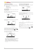
Page 75: ...185 Gas valve flow chart signal Pipe 38 39 ...

Page 76: ...Pipe Holder Valve screws ELV Functional Part Generator Mode Component Point Value Type of Measure Notes ELV command ON TIG DC ELV 39 38 39 38 2Vdc 24Vdc Torch button switch OFF Torch switch pres sed Active for few second if machine is not loaded Note Torch button pressed Active for few second if machine is not loaded GAS VALVE DISMONTLING REPLACEMENT ...

Page 77: ...art buttom from output filter card 15 14 516 bus card 15 14 431 15 14 415 LOCATION 3rd position in rack system from front panel between hf card and analog card Connected on bus board 15 14 431 and via ribbon cable to the main inverter Each pc b on rack have his right position not possible wrong placing DISMANTLING NOTE remove the screw at base of plastic support then extract the pcb and when acces...

Page 78: ...N L9 ON This diodes is blinking Correct comunication DSP uC This diodes is blinking slowly 5Vdc voltage supply ON L10 ON 3 3Vdc voltage supply ON L11 ON 1 9Vdc voltage supply ON L12 ON 5Vdc isolated voltage supply ON L5 ON Firmware updated ON L1 OFF L2 OFF L3 OFF L4 OFF These diodes are blinking when fir ware is updating Hardware reset uC ON SW1 Pressed Hardware reset DSP ON SW2 Pressed When SW1 o...

Page 79: ...189 CN6 15 14 415 CN3 15 14 431 FLAT A FLAT B Inverter commands Boost commands ...

Page 80: ...190 By pass relais flow chart Gas valve ELVI Fan M1 and M2 command signal ...

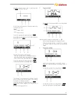
Page 81: ...191 HF command signal AC command signal Torch switch buttons signals ...

Page 82: ...with pfc power stage switch DISMANTLING NOTE remove the screw at base of plastic support then extract the pcb and when accessible disconnect CN1 and CN2 Pay attention during dismantling and reassembling of CN3 ribbon cable to the hot glue present First remove with properly tool the glue then lift up flat cable without tearing NOTE the pc board has got few pre adjusted trimmers don t move from fact...

Page 83: ...193 Input voltage after EMC filter ON CN1 1 CN1 3 230Vac DC LINK ON CN2 1 CN2 3 375Vdc Ref power supply DC Bus voltage Flat with 15Vdc power supply from input filter card ...

Page 84: ...ouble effect on output voltage useful for strong and sure ARC ignition LOCATION at 1st position in rack system from left the first one after the front panel before the h f card The pcb on rack have fix position not possible wrong slot placing DISMANTLING NOTE remove the screw at base of plastic support then extract the pcb and when accessible disconnect CN2 CN3 CN4 The connector pinning has been d...

Page 85: ...e OFF D7 A K 0 45Vdc D8 A K 0 45Vdc D9 A K 0 45Vdc D10 A K 0 45Vdc D12 A K 0 45Vdc D13 A K 0 45Vdc D14 A K 0 45Vdc D15 A K 0 45Vdc IGBT OFF IG1 E C E G 0 5Vdc 2 2kohm IG2 E C E G 0 5Vdc 2 2kohm Diode IGBT OFF D3 D17 A K A K 0 5Vdc 0 5Vdc Mosfet OFF MF1 S D S G 0 55Vdc 100kohm Note MF1 ...

Page 86: ...sconnect FN1 FN2 Pay attention to correct winding H F sense mark on cables is recommended NOTE a relay reverse the polarity sense in order to improve the striking in DC as well AC Three leds shown L1 VCC L2 RF TURN ON L3 POLARITY RELAY COMMAND L1 L2 D1 D3 D4 FN1 FN2 L3 D12 FN1 white faston FN2 red faston Functional Part Generator Mode Component Point Value Type of Measure Notes Diodes OFF D1 D3 D4...

Page 87: ...197 Notes HF command signal HF WAVEFORM WARNING Use a probe with a minimum attenuation of x100 Red faston White faston ...

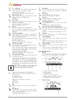
Page 88: ...198 HF pulse in TIG AC HF pulse in TIG DC ...

Page 89: ...tal control card LOCATION right upper section the pc board has got a trapezoidal shaping DISMANTLING NOTE remove connectors CN1 to CN4 and wire on C1 Four screws fix the pcb on aluminium frame Different lay out connectors avoid wrong replacement NOTE two led shown which diagonal is switched if DC DC or blinking in case of AC welding MF1 TR2 TR1 Z4 D8 Z9 Z10 Z5 Z7 Z6 D9 L2 L3 TR3 TR4 Z8 Z11 Functio...

Page 90: ...his LED is ON in Sitck DC TIG DC TIG AC part This LED is ON in Sitck DC TIG AC part This Leds blin king in Stick AC TIG AC Before wel ding in Stick AC is only L2 ON whe reas in TIG AC is only L3 ON CN1 1 Not use CN2 1 e CN2 4 Input NTC CN1 2 COM AC CN1 3 GND_S CN3 1 e CN3 2 Thermostat input CN1 4 15Vdc CN1 5 Output Ther 2 15 14 419 not use CN4 1 COM_AC_GA CN1 6 Output Ther 1 15 14 419 CN4 3 COM_AC...

Page 91: ...on display s contest LOCATION at top front side DISMANTLING NOTE unscrews the two screws present on front side then pivot and extract Remove CN3 and earth wire NOTE a piezo buzzer present for button pressing The panel is given assembled complete with pc board 15 14 343 and 15 14 342 display 2 5 and metal aluminium serigraphy Display not available separately Front panel present on first product edi...

Page 92: ...disabled function based on display s contest two button for store and recall programs LOCATION at top front side DISMANTLING NOTE unscrews the two screws present on front side then pivot and extract Remove CN1 and earth wire NOTE a piezo buzzer present for button pressing The panel is given assembled complete with pc board 15 14 517 display 3 5 and metal aluminium serigraphy Display not available ...

Page 93: ... alarm state Output power enable with open circuit voltage limitation ON L3 ON Red MMA or TIG with trigger press 5Vdc voltage supply ON L4 ON 3 3Vdc voltage supply ON L5 ON CAN BUS comunications ON L6 ON L7 ON Blinking when there is a CAN BUS comunica tions Serial Comunications ON L11 ON L12 ON Blinking when there is a serial comunication ...

Page 94: ...s information is therefore necessary before changing the card to contact the service at service selcoweld com for testing and management of board to be replaced Connectors pinning available at par Connectors CN7 CN8 CN9 CN10 CN11 CN12 CN13 CN14 CN15 CN16 CN17 Functional Part Generator Mode Component Point Value Type of Measure Notes 15Vdc CAN bus voltage supply ON CN8 CN8 1 CN8 2 15Vdc Supply volt...

Page 95: ...e signal thanks to I V converter HALL probe Twisted winding for power supply and Iout signal Output current value could be measured between CN10 7 CN10 3 CN10 Pcb 15 14 431 using below conversion for mule Vmeasured Iout 74 Vdc Iout Vmeasured Measured value example 50A 0 675Vdc 0 675Vdc 100A 1 351Vdc 1 320Vdc 150A 2 027Vdc 1 953Vdc 180A 2 432Vdc 2 365Vdc ...

Page 96: ...ted to DC digital multimeter Pay particular attention in order to avoid accidentaly short circuit between therminals leads ATTENTION AVOID TO SHORT CIRCUIT DURING MEASUREMENT PAY ATTENTION TO NOT DAMAGE CONNECTORS CN10 Pin 10 Pin 5 Pin 10 Pin 9 Pin 8 Pin 7 Pin 6 Pin 5 Pin 4 Pin 3 Pin 2 Pin 1 ...

Page 97: ...OUTPUT CONNECTOR CHECK Output connector and switch torch button could be placed on CN7 bus card side CN7 CN7 1 CN7 5 CN7 4 CN7 8 ATTENTION AVOID TO SHORT CIRCUIT DURING MEASUREMENT PAY ATTENTION TO NOT DAMAGE CONNECTORS CN7 ...

Page 98: ...tch pressed UP torch switch ON TIG CN7 CN7 2 CN7 5 5Vdc 0Vdc UP torch switch released UP torch switch pressed During this operation the display shows increasing current value DOWN torch switch ON TIG CN7 CN7 3 CN7 5 5Vdc 0Vdc DOWN torch switch released DOWN torch switch pressed During this ope ration the display shows decrease current value Note Measure done mit plugged torch PT SWITCH DOWN SWITCH...

Page 99: ...wo screws connector CN1 2 3 and winding to be removed The replacement will be easier if front command display and plastic frontal mask will be removed Then unscrews the plastic profile from aluminium frame and copper bar connection with H F transformer The pcb will placed as required for inspection or replac ment NOTE this pcb need to be evaluate mainly for visual inspection measure should be plac...

Page 100: ...dc UP torch switch released UP torch switch pressed During this ope ration the display shows increasing current value DOWN torch switch ON TIG CN7 CN4 3 CN4 5 5Vdc 0Vdc DOWN torch switch released DOWN torch switch pressed During this ope ration the display shows decrease current value Note It is recommend to take measurement directly on CN7 Pcb bus 15 14 431 In case of missing measurement proceed ...

Page 101: ...1 FAN REPLACEMENT 1 Dismontling rear back panel Screws 2 Disconnect connector CN14 or CN15 from bus 15 14 431 15 14 431 Connectors for fan power supply 3 Unscrew fan Screws Screws 4 Remove and replace fan ...

Page 102: ... on set up 704 press directly button save exit The calibration is done Fig 13 A Fig 13 B 13 2 Current calibration to be done after 704 calibration Set the power source in TIG DC mode not particular adjustment are required as well setting Suggested current value to do the cali bration is at 200 150 amp As alternative could be used the MMA process connected to relative static load in case consult se...

Page 103: ...ng of the generator With the generator turned on the fans work to speed up the cooling of the generator If the alarm is present just switching on generator status cold the T1 is defective or a cable connection is discon nected See Test on Primary Thermic sensor E03 Temperature alarm 3 NTC2 and T2 secondary side alarm If the alarm is tripped for a temperature rise due to extra duty cycle working ti...

Page 104: ...14 415 E17 Communication alarm μP DSP 15 14 415 internal failure Wrong software download Control software release par 501 pwd 358 set up serv update software reset 15 14 415 repair E18 Program not valid alarm Recall of stored program in wrong sequence as program 2T to 4T or AC to DC Recall during welding of com patible programs Check sto red program In case overwrite with new program E19 System co...

Page 105: ...pply alarm Input power supply out of admited range Check input line status input card 15 14 443 main switch The checks should be done with machine loaded on output will help on discove ring floating voltage E40 System power supply alarm Missing phase on input power supply Check input line status input card 15 14 443 main switch The checks should be done with machine loaded on output will help on d...

Page 106: ...sage and complete block of welding process In end out time filter avoid wrong signal due to start and stop welding process Alarm Description E54 Current level exceeded Alarm E62 Current level exceeded Warning E55 Current level exceeded Alarm E63 Current level exceeded Warning E56 Voltage level exceeded Alarm E64 Voltage level exceeded Warning E57 Voltage level exceeded Alarm E65 Voltage level exce...

Page 107: ...occurring between the electrode and the piece protecting the gun electrode and welder and guaranteeing safety in the condition that has occurred ON Antisticking active OFF Antisticking not active 0 1 2 0 The short circuit time before the antisticking function intervenes Default 0 5s 501 Info Allows the display of a set of information related to the system Consult the INFO screen 502 Alarm queue Al...

Page 108: ...ltage of the power source Minimum 0 0V Maximum 99 9V Default 45V 501 Info Allows the display of a set of information related to the system 502 Alarm queue Allows the intervention of an alarm to be indicated and provides the most important indications for the solution of any problem encountered Consult the Alarms screen section 656 Management WU Off No active Syn Sinergic mode START WU Torch button...

Page 109: ... to disenable the control of the guard limits in advance of the natural closing of the weld Makes it possible to filter the extinction phase consult the Guard limits section Minimum 0 0s Maximum 10 0s Default 2 0s 15 3 INFO screen Lets you display of a series of system data 1 System type board 2 Board Control board 3 Software Software version Control board 4 S N Serial number 5 Power supply Power ...

Page 110: ...170 150A 180 180A Adjustment range I2 MMA 3 150A 3 180A TIG 3 170A 3 220A Open circuit voltage Uo 80V 80V Peak voltage Up 10 1kV 10 1kV IP Protection rating IP23S IP23S Insulation class H H Dimensions lxdxh 500x190x400 mm 500x190x400 mm Weight 18 8 Kg 18 8 Kg Manufacturing Standards EN 60974 1 EN 60974 3 EN 60974 1 EN 60974 3 EN 60974 10 EN 60974 10 Power supply cable 3x2 5 mm2 3x2 5 mm2 Length of...

Page 111: ...ktrogeräte die am Ende ihrer Lebensdauer angelangt sind gesondert gesammelt und einer Recycling und Entsorgungsstelle über geben werden Der Eigentümer des Geräts muss sich bei den Örtlichen Verwaltungen über die autorisierten Sammelstellen informieren Durch die Einhaltung der Europäischen Richtlinie schützen Sie die Umwelt und die Gesundheit Ihrer Mitmenschen Ne pas éliminer les équipements électr...

Page 112: ...Gamme du courant maximum et minimum et de la tension conventionnelle de charge corre spondante 12 Symbole du cycle d intermittence 13 Symbole du courant nominal de soudage 14 Symbole de la tension nominale de soudage 15 16 17 Valeurs du cycle d intermittence 15A 16A 17A Valeurs du courant nominal de soudage 15B 16B 17B Valeurs de la tension conventionnelle de charge 18 Symbole de l alimentation 19...

Page 113: ...223 19 SCHEMI ELETTRICI E DI COLLEGAMENTO WIRING DIAGRAMS AND CONNECTION GENESIS 1700 AC DC FP279 ...

Page 114: ...224 GENESIS 2200 AC DC FP279 ...

Page 115: ...225 GENESIS 1700 AC DC FP216 ...

Page 116: ...226 GENESIS 2200 AC DC FP216 ...

Page 117: ...ventilatore scheda di potenza GND_Power supply board fan command 51 Fase U Phase U 53 Fase V Phase V 61 Vbus Vbus 63 0_Vbus 0_Vbus 64 Vbus Vbus 66 0_Vbus 0_Vbus 70 S potenza di sovrapposizione S superimposition power 72 S potenza di sovrapposizione S superimposition power 74 Sout potenza di sovrapposizione Sout siperimpotion power 81 Comunicazione I2C I2C communication 82 Comunicazione I2C I2C com...

Page 118: ...228 20 CONNETTORI CONNECTORS GENESIS 1700 AC DC FP279 GENESIS 2200 AC DC FP279 ...

Page 119: ...229 GENESIS 1700 AC DC FP216 GENESIS 2200 AC DC FP216 ...

Page 120: ...230 21 LISTA RICAMBI SPARE PARTS LIST 55 08 013 55 08 014 GENESIS 1700 AC DC FP279 GENESIS 2200 AC DC FP279 ...

Page 121: ...Anschluss 1 8 Stopfen Pvc gewebeschlauch 5x11 L 1 70m Pvc gewebeschlauch 5x11 Brenner verbindungskit Bedienungsanweisungen A Bedienungsanweisungen B FRANÇAIS Carter supérieur Carter inférieur Couverture Manche Plaque frontale Plaque arrière Panneau latéral droit Panneau latéral droit G2200 AC DC Panneau latéral gauche Panneau latéral gauche G2200 AC DC Transformateur puissance Transformateur Induc...

Page 122: ...232 55 08 022 55 08 023 GENESIS 1700 AC DC FP216 GENESIS 2200 AC DC FP216 ...

Page 123: ...ile vorne Kit hintere kunststoffteile Wärmefühler Wärmefühler Wärmefühler Verbinderstopfen Ventilator Anschluss 1 8 Stopfen Pvc gewebeschlauch 5x11 L 1 70m FRANÇAIS Carter supérieur Carter inférieur Couverture Manche Plaque frontale Plaque arrière Panneau latéral droit Panneau latéral droit G2200 AC DC Panneau latéral gauche Panneau latéral gauche G2200 AC DC Transformateur puissance Transformateu...

Page 124: ... A PASSER AU NUMÉRO DE FAX 39 0499413950 POUR DEMANDER L ENVOI URGENT DES PIÈCES DE RECHANGE SOUS GARANTIE SELON BARREMENT ADJUNTAR A LAS PIEZAS DEFECTUOSAS REMITIR AL NUMERO FAX 39 0499413950 PARA REQUERIR EL ENVÍO URGENTE DE REPUESTOS EN GARANTÍA SEGÚN LISTADO PEZZI SOSTITUITI IN GARANZIA PARTS REPLACED UNDER WARRANTY UNTER GARANTIE AUSGEWECHSELTE TEILE PIÈCES REMPLACÉES SOUS GARANTIE PIEZAS SUS...

Reviews: