
The KFT-2410R supply was designed for industrial
installations where operation is continuous and requires
reliable components.
Built with the most modern techniques of switching with high
performance and small footprint supplys, and excellent
stabilization and regulation.
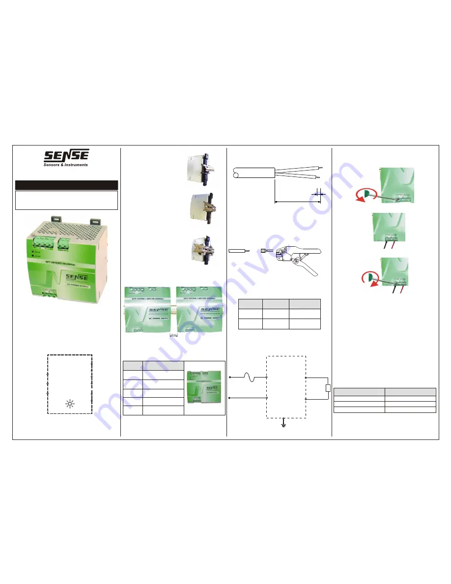
Supply Fixing:
Fixing the supply internally in the
panel must be made using 35mm
rails (DIN-46277).
Follow the procedures below:
1° Place only the supply upper
bracket on the rail . (Fig.03)
2 º Lower the supply until it fully
engages on the rail. (Fig. 04).
3º We recommend installing stops
so that the supply does not slide on
the rail. (Fig 05).
Horizontal mounting:
We recommend mounting in a
horizontal position in order to
ensure improved air circulation and
that the panel is provided with a ventilation system to prevent
overheating of the internal components.
Note:
We recommend also leaving a gap of at least 20mm
from one supply to another, in order to improve the cooling.
Electric Installation:
The supply has 9 terminals according to the table below:
Terminal
Description
1 and 2
Positive output 24 Vdc
3 and 4
Negative output 24Vdc
5 and 6
Alarm
7 and 9
AC input
8
Ground
Wire Preparation:
Do the ends of the wires according to the drawing below:
Be careful when removing the protective cover not to make
small cuts in the wires, as this may cause short circuit.
Note:
The minimum wire size for an output current of 10A must
be 1mm
2
.
Procedures:
Remove the protective cover, insert the terminals and crimp
them. If you want to tin the ends for better grip.
Terminals:
To avoid problems of poor contacts and shorting advise using
pre-insulated terminals crimped on the wires.
AC input:
The KFT-2410R power supply has an automatic selection
circuit for 110 or 220Vac (full range), which prevents damage
to the supply with the improper selection / connection of the
equipment.
Voltage
Power
Current
110 Vac
187 VA
1,7 A
220 Vac
220 VA
1 A
Note
: The values shown in the table above are for the condition
of maximum load (10A) in the supply.
AC Input Protection:
We recommend using the electrical circuit that supplies the
unit by a protection circuit breaker or fuse.
Supply Terminals:
• Loosen the terminal screw using a switch with a diameter of
3 to 3,5mm.
• Insert the wire with the terminal already applied, from the
bottom of the terminal.
• Tighten the terminal screw, and repeat for the other
terminals.
• Verify that actually wires are securely attached by pulling
them lightly.
Output Voltage:
The unit has a stabilized output voltage regardless of the
current drawn.
The direct current output, positive (1 or 2) and negative (3 or
4) terminals of the unit provides 24VDC with capacity for up to
10A.
We recommend its use for automation circuits supply such as:
electronic sensors
PLC input or output cards.
electronic modules
auxiliary relays
Current loops
• Industrial networks Profibus DP and DeviceNet standards
Signalling Led:
The supply has on its front a two-color LED whose function is
described in the table below:
Led Status
Function
Green on
Normal operation
Green off
stand by
Red on
Short-circuit or overload
Note:
The standby condition (sleep) occurs when the supply is
working in parallel with each other and with lower output
voltage than other supplys, and this condition does not provide
(splits) current to the load.
Rua Tuiuti, 1237 - CEP: 03081-000 - São Paulo
Tel.: 11 2145-0444 - Fax.: 11 2145-0404
vendas@sense.com.br - www.sense.com.br
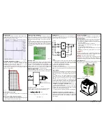
INSTRUCTIONS MANUAL
Switching Power Supply
KFT-2410R/110-220Vac
Tab. 8
Fig.7
1 2 3 4 5 6
7 8 9
Fig. 1
Pic. 2
Alicate ZA3
Pic. 10
Pic. 11
+
-
5
F
110 ou
220Vca
F
N
40
5
Pic. 9
Fig. 3
Fig. 4
Fig. 6
FONTE DE ALIMENTAÇÃO
LED
F
F
N
CORRENTE ALTERNADA
110 ou 220Vca
EM
ENTRADA
CORRENTE CONTINUA
SAÍDA
-
+
24Vcc
-
+
ALARME
Fig. 5
EA3000830- Rev. Bi - 09/15
2
1 .
b
a
T
Pic. 13
Fig. 14
Fig. 15
Fig. 16
Tab. 17


