background image

Sensor

Link

Operators Manual

True RMS Radio Ampstik

Radio Linked Multiple Reading Ammeter

Region One
Region Two
Region Three

Summary of Contents for 6-120

Page 1: ...SensorLink Operators Manual True RMS Radio Ampstik Radio Linked Multiple Reading Ammeter Region One Region Two Region Three ...

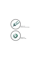
Page 2: ...Model 8 120 Sensor Transmitter Meter Model 8 121 Receiver Display ...

Page 3: ... 120 50HZ 869 8 120 50HZ AUS 8 120 60HZ 869 8 120 FRG 8 121 8 121 EURO 8 121 AUS 8 121 869 8 121 FRG Table of Contents Page Safety Information 3 Specifications 4 Temperature Applications 5 Operating Instructions 6 7 FCC Statements 7 High Voltage Operation 8 Battery Replacement 8 Cleaning 8 Warranty 10 Quality Assurance Back Cover Page 2 ...

Page 4: ...g parts and does not require clamping onto the wire The case is water resistant and will withstand high physical impact The following specifications apply Page 3 This equipment has been tested and found to comply with the limits for a Class B digital device pursuant to Part 15 of the FCC rules These limits are designed to provide reasonable protection against harmful interference in a residential ...

Page 5: ...t Operating Temperature 4 to 140 F 20 to 54 C Storage Temperature 140 to 158 F 40 C to 70 C Display Five Digit Display Type of Reading Four Readings Housing Shock Water resistant molded urethane Hotstick Mounting Universal Chuck Adapter Hotstick not included Battery 9 volt 1 ea in Transmitter Receiver Battery Life Five days continuous use Indoor Outdoor Use Relative Humidity 90 non condensing Alti...

Page 6: ...ng a Lithium long life battery the Radio Ampstik can operate from or 30 C 22 F to 60 C 140 F 9 volt Lithium batteries are the same long life batteries used in smoke detectors They sell by the brand names UltraLife and Energizer Note Alkaline operating time reduced to 25 at 4 F or 20 C Lithium operating time reduced to 75 at 4 F or 20 C Page 5 ...

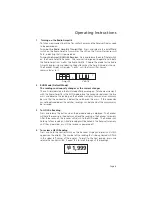
Page 7: ...the Radio Ampstik in the RUN mode place the conductor between the two arms and observe the reading on the Receiver s display For maximum accuracy be sure that the conductor is below the notches on the arms If the conductor cannot be placed below the notches readings can be taken but the accuracy may be lessened 3 To HOLD a Reading Press and release the button when the desired reading is diplayed T...

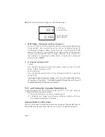
Page 8: ...witch on the Receiver Display and scroll to the OFF option Release the control switch Sensor Transmitter Press and hold the control switch until the LED goes to solid RED Release the control switch The Radio Ampstik Receiver Display will turn off automatically after 60 minutes of inactivity The Radio Ampstik Transmitter will turn off automatically after 20 minutes of inactivity X XXX XX X FCC and ...

Page 9: ... edges of the compartment and reinstall the four cover screws Take care to avoid over tightening the screws Always reuse the screws provided and do not damage or lose the o ring seal on each screw Receiver Display DO NOT unscrew the four screws on the corners of the front panel Loosen the thumb screw located on the front middle of the unit Remove the old battery Snap the fresh battery to the conne...

Page 10: ...Page 9 ...

Page 11: ...ument 2 Subjected to misuse negligence or accident or 3 Connected installed adjusted or used otherwise than in accordance with the instructions furnished by SensorLink This Warranty is in lieu of any other warranty expressed or implied SensorLink reserves the right to make any changes in the design or construction of its instruments at any time without incurring any obligation to make any change w...

Page 12: ...ts of that standard Transmitter Model 8 120 Serial Number _______________________________ Receiver Model 8 121 Serial Number __________________________________ I hereby certify that the True RMS Radio Ammeter listed above has passed all tests defined in the SensorLink standard I also certify that I have reviewed the standard and test procedure and that they are sufficient in determining compliance...

Reviews: