background image

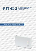
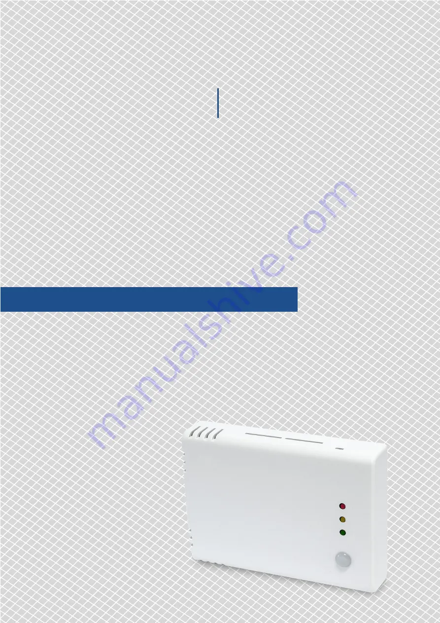
Mounting and operating instructions

RSTHX-2 

COMBINED TEMPERATURE AND 

RELATIVE HUMIDITY ROOM 

TRANSMITTER 

Summary of Contents for RSTHX-2

Page 1: ...Mounting and operating instructions RSTHX 2 COMBINED TEMPERATURE AND RELATIVE HUMIDITY ROOM TRANSMITTER ...

Page 2: ...TENDED AREA OF USE 4 TECHNICAL DATA 4 STANDARDS 4 OPERATIONAL DIAGRAMS 5 WIRING AND CONNECTIONS 5 MOUNTING INSTRUCTIONS IN STEPS 6 OPERATING INSTRUCTIONS 8 VERIFICATION OF INSTALLATION INSTRUCTIONS 9 TRANSPORT AND STORAGE 9 WARRANTY AND RESTRICTIONS 9 MAINTENANCE 9 RSTHX 2 COMBINED TEMPERATURE AND RELATIVE HUMIDITY ROOM TRANSMITTER ...

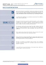
Page 3: ...ry as possible avoid condensation All installations shall comply with local health and safety regulations and local electrical standards and approved codes This product can only be installed by an engineer or a technician who has expert knowledge of the product and safety precautions Avoid contacts with energised electrical parts Always disconnect the power supply before connecting servicing or re...

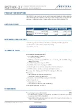
Page 4: ...uts 0 10 VDC mode RL 50 kΩ 0 20 mA RL 500 Ω PWM open collector type PWM Frequency 1 kHz RL 50 kΩ PWM voltage level 3 3 or 12 VDC Selectable temperature range 0 50 C Selectable relative humidity range 0 100 Ambient light sensor with adjustable active and standby level 3 LEDs for status indication with adjustable light intensity Accuracy 0 4 C range 0 50 C 3 rH range 0 95 rH Enclosure rear plate pla...

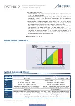
Page 5: ...ansducers with integrated or remote signal conditioning WEEE 2012 19 EC RoHs Directive 2011 65 EC OPERATIONAL DIAGRAMS 10 0 50 20 30 40 50 60 70 80 90 100 Minimum range Minimum alert Maximum alert Analogue modulating outputs T C rH Maximum range Out of range Within range Alert range Alert range Out of range LED indication T default and rH WIRING AND CONNECTIONS Article type RSTHF 2 RSTHG 2 VIN 18 ...

Page 6: ...t damage to the connected devices MOUNTING INSTRUCTIONS IN STEPS Before you start mounting the unit read carefully Safety and Precautions Choose a smooth surface for installation a wall panel and etc Follow these steps 1 Using a flat screwdriver remove the front white cover by releasing the snap fits on its both sides see Fig 1 Snap fits release 2 Insert the cables through the opening on the rear ...

Page 7: ...etting refer to the product Modbus register map For the complete Modbus register data refer to the product Modbus Register Map which is a separate document attached to the article code on the website and contains the registers list Products with earlier firmware versions may not be compatible with this list NOTE 5 Optional settings To assure correct communication the NBT needs to be activated in o...

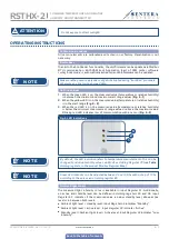
Page 8: ...e temperature or relative humidity is below the minimum measurement range value or above the maximum value Blinking red LED indicates loss of communication with a sensor Fig 5 3 Fig 5 LED indications 3 2 1 By default the LED indication refers to temperature measurements This can be changed to relative humidity values via Modbus Holding Register 79 see Table Holding registers in the product Modbus ...

Page 9: ...in manufacturing Any modifications or alterations to the product after the date of publication relieve the manufacturer of any responsibilities The manufacturer bears no responsibility for any misprints or mistakes in this data MAINTENANCE In normal conditions this product is maintenance free If soiled clean with a dry or damp cloth In case of heavy pollution clean with a non aggressive product In...

Reviews: