background image

AsteRx-U

User Manual

Summary of Contents for AsteRx-U

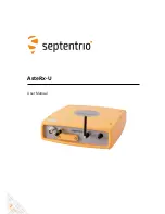
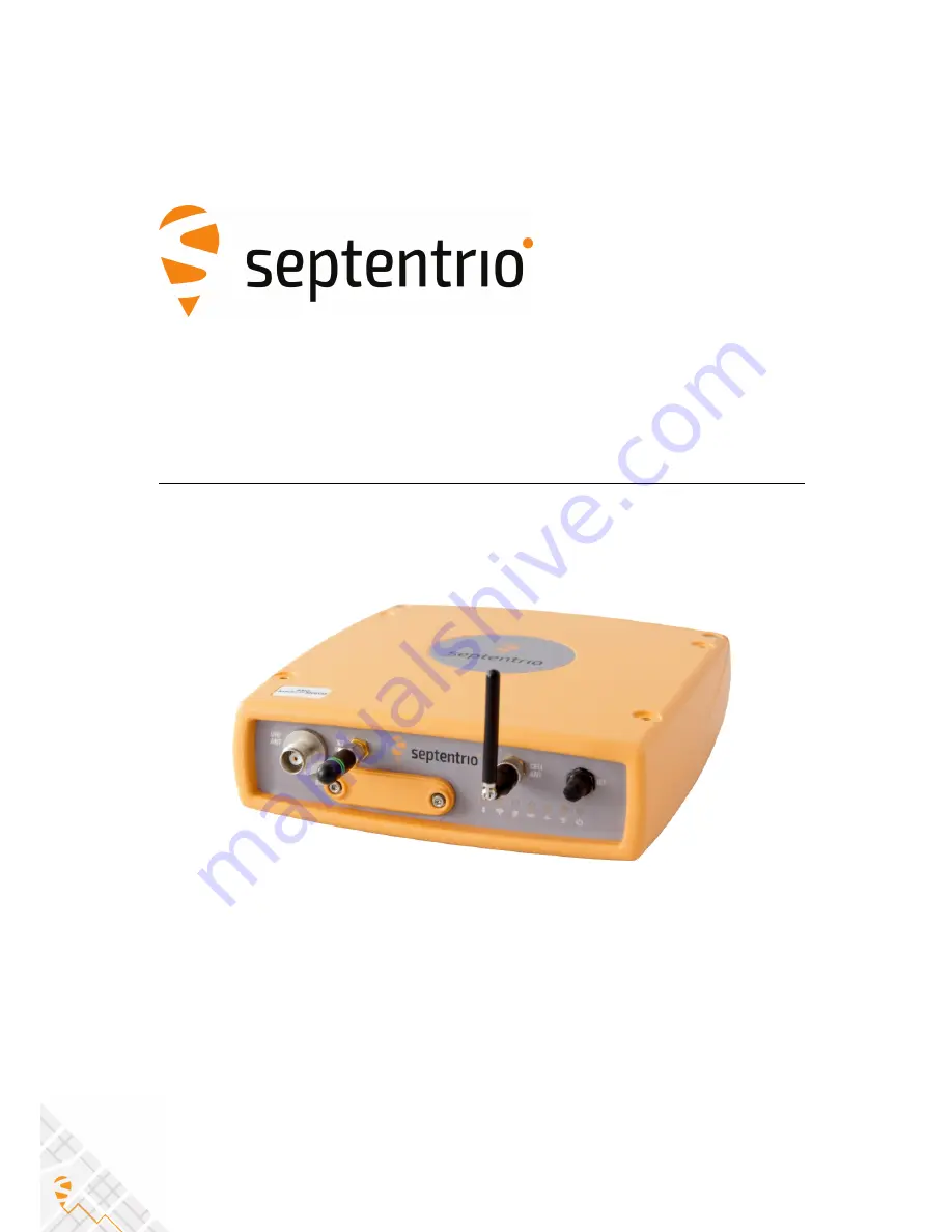
Page 1: ...AsteRx U User Manual ...

Page 2: ...ver the particular AsteRx U you purchased may not support functions specific to certain variants While we try to keep the manual as complete and up to date as possible it may be that future features functionality or other product specifications change without prior notice or obligation The information contained in this manual is subject to change without notice Copyright 2000 2017 Septentrio NV SA A...

Page 3: ...nal items 15 3 Quick start 16 3 1 POWERING THE ASTERX U 16 3 2 CONNECTING AN ANTENNA 17 3 3 CONNECTING TO THE ASTERX U VIA THE WEB INTERFACE 17 3 3 1 Using the USB cable 17 3 3 2 Using the Ethernet cable 19 3 3 3 Over WiFi 20 3 4 HOW TO CONFIGURE SBF AND NMEA OUTPUT 21 3 4 1 Output over a serial COM connection 21 3 4 2 Output over Ethernet 25 3 4 3 Output over bluetooth 28 4 Rover operation 32 4 1...

Page 4: ...BLEM DIAGNOSIS 66 6 4 ACTIVITY LOGGING 68 7 Receiver Administration Operations 69 7 1 HOW TO CHANGE IP SETTINGS OF THE ASTERX U 69 7 2 HOW TO CONFIGURE DYNAMIC DNS 70 7 3 HOW TO CONTROL ACCESS USING THE ASTERX U FIREWALL 71 7 4 HOW TO UPGRADE THE FIRMWARE OR UPLOAD A NEW PERMISSION FILE 72 7 5 HOW TO SET THE ASTERX U TO ITS DEFAULT CONFIGURATION 74 7 6 HOW TO RESET THE ASTERX U 74 7 7 HOW TO COPY ...

Page 5: ...is the prevention of waste electrical and electronic equipment WEEE and in addition the reuse recycling and other forms of recovery of such wastes so as to reduce the disposal of waste If purchased in the European Union please return the receiver at the end of its life to the supplier from which it was purchased 1 1 3 Safety information Statement 1 The power supply provided by Septentrio if any sh...

Page 6: ...rio com Europe Septentrio NV Phone 32 16 300 800 Greenhill Campus Fax 32 16 221 640 Interleuvenlaan 15i sales septentrio com 3001 Leuven Belgium North and South America Septentrio Inc Phone 1 310 541 8139 23848 Hawthorne Blvd sales septentrio com Suite 200 Torrance CA 90505 USA Asia Pacific Septentrio Phone 852 9095 5066 Unit 1901 Hua Fu Commercial Building sales septentrio com 111 Queen s Road Wes...

Page 7: ... robust industrial performance Integrated cellular modem Bluetooth WiFi and optional UHF radio 2 1 1 GNSS 544 hardware channels for simultaneous tracking of all visible satellite signals Supported signals GPS L1 L2 L5 GLONASS L1 L2 L3 GALILEO E5ab AltBoc E6 BEIDOU B1 B2 B3 IRNSS L5 QZSS L1 L2 L5 Galileo Beidou and IRNSS are optional features All in view SBAS EGNOS WAAS GAGAN MSAS SDCM incl L5 trac...

Page 8: ...7 s Velocity accuracy 0 03 m s Attitude accuracy antenna separation Heading Pitch Roll 1 m 0 15 0 25 10 m 0 03 0 05 Connectivity 3 hi speed serial ports RS232 Ethernet port TCP IP and UDP Full speed USB host and device 2 Event markers xPPS output max 100 Hz Integrated Bluetooth 2 1 EDR 4 0 Integrated Quadband Cellular Modem EDGE 2G 3G 3 5G Integrated WiFi 802 11 b g n Integrated UHF 406 470 MHz As...

Page 9: ... AsteRx U variants The AsteRx U is available in three variants Variant Main features Part number AsteRx U 410121 Integrated cellular modem Integrated WiFi modem Integrated Bluetooth modem AsteRx U UHF 410119 Integrated cellular modem Integrated WiFi modem Integrated Bluetooth modem Integrated UHF radio with front panel connector AsteRx U MARINE 410120 Integrated cellular modem Integrated WiFi mode...

Page 10: ...STERX U DESIGN 2 3 AsteRx U design 2 3 1 Front panel The front panel layout of the AsteRx U with attached Bluetooth WiFi and Cellular antennas is shown in Figure 2 1 Figure 2 1 AsteRx U front panel layout 10 ...

Page 11: ...ted green Off Not logging On Logging active disk is mounted Blinking slowly Logging active disk space is low Blinking quickly Disk is full or not mounted green Off No reception of correction data Blinking Blinks on reception of correction data green Off No PVT available On PVT available green Off UHF radio modem disabled On UHF radio modem in search mode Blinking slowly Data package sent received ...

Page 12: ...ments for each socket can be found in the Appendix Figure 2 2 AsteRx U rear panel layout 2 3 4 SIM card slot The SIM card can be inserted into the slot in the front panel of the AsteRx U as shown in Figure 2 3 Important Only insert or remove the SIM card while the unit is powered down Figure 2 3 SIM card slot on AsteRx U 12 ...

Page 13: ...ets which can be fitted to the unit as shown in Figure 2 4 Figure 2 4 Mounting brackets fitted to AsteRx U 2 3 6 Internal memory The AsteRx U has an 8 GB Memory for internal data logging Data can be logged in SBF or NMEA format and may be retrieved via the logging tab of the web interface 13 ...

Page 14: ...2 4 SHIPPING CASE CONTENTS 2 4 Shipping case contents 2 4 1 Supplied as standard The following items with their part numbers are supplied as standard with the AsteRx U 14 ...

Page 15: ...2 4 SHIPPING CASE CONTENTS 2 4 2 Optional items The following items with their part numbers can be optionally purchased for use with the AsteRx U 15 ...

Page 16: ...ed open ended power cable the receiver can be powered by applying 6 to 36 V via the power in wire The receiver can also be powered using the power adapter optionally available The power socket is indicated in Figure 3 1 Figure 3 1 Rear panel power socket There is a power button on the front panel as shown in Figure 3 2 which you may also have to press If the AsteRx U loses power while the power bu...

Page 17: ...sing the receiver s on board Web Interface The connection can be made using either USB Ethernet or WiFi The following sections describe each of the connection methods 3 3 1 Using the USB cable Connect the combined USB Ethernet cable to the connector labelled ETH USB on the rear panel of the AsteRx U and indicated in Figure 3 4 Figure 3 4 Rear panel USB and Ethernet socket The first time that the US...

Page 18: ...ons as network adapter and the DHCP server running on the receiver will always assign the AsteRx U the IP address 192 168 3 1 To connect to the AsteRx U you can then simply open a web browser using the IP address 192 168 3 1 as shown in Figure 3 6 Figure 3 6 Connect to the Web Interface of the AsteRx U over USB using the IP address 192 168 3 1 on any web browser 18 ...

Page 19: ...3 7 Figure 3 7 Rear panel USB and Ethernet socket Step 2 Open a web browser and connect to the AsteRx U By default the AsteRx U has a DHCP address http Asterx U xxxxxxx where xxxxxxx are the 7 digits of the AsteRx U serial number The serial number can be found on a sticker on the corner of the outer casing of the receiver Figure 3 8 shows a screenshot of an Ethernet connection to a receiver with s...

Page 20: ...r of the AsteRx U can be found on an identification sticker on the receiver housing Select and connect to the AsteRx U as shown in Figure 3 9 Figure 3 9 Select the AsteRx U from the list of detected wireless signals and connect When your PC is connected to the AsteRx U WiFi signal you can open a web browser using the IP address 192 168 20 1 as shown in Figure 3 10 Figure 3 10 Connect to the Web Int...

Page 21: ...able to an RS 232 compatible secondary device1 Step 1 Configure the serial COM port The COM port of the AsteRx U should be configured with the same baud rate and flow control setting of the coupled device These settings can be configured via the Communication tab as shown in Figure 3 11 In this example COM3 is set with a speed of 19200 baud Figure 3 11 Configure the baud rate and flow control of the Ast...

Page 22: ...MEA In the NMEA SBF Out tab clicking on New NMEA Stream will guide you through the steps needed to configure NMEA output as shown in Figures 3 12 and 3 13 Figure 3 12 Selecting to output NMEA data on COM3 Figure 3 13 Selecting to output the GGA NMEA message every second 22 ...

Page 23: ...cond output stream can be configured In the example shown in Figures 3 14 and 3 15 the PVTCartesian SBF data block will be output over COM1 once per second Figure 3 14 Selecting to output SBF data on COM1 Figure 3 15 Selecting to output the PVTCartesian SBF block every second 23 ...

Page 24: ...ure 3 16 Figure 3 16 Summary of all configured data output streams Figure 3 17 shows the actual data output NMEA is in ASCII and is thus readable unlike SBF which is formatted in binary In this example the serial COM was connected to a PC via a USB adapter which maps the serial connection to a virtual COM9 of the PC Figure 3 17 Example showing output NMEA GGA left panel and SBF PVTCartesian right p...

Page 25: ... 3 18 port 28785 has been configured as connection IPS1 in TCP2Way mode so data can be received as well as transmitted over the connection It is advisable to select a higher range port to avoid those reserved for other purposes such as the webserver and FTP Also port 28784 is reserved by default on the AsteRx U for commands Note that a new IP port can also be configured by followings the sequence of...

Page 26: ...stream and follow the sequence of windows to configure the data you want to output In the example shown in Figure 3 19 the NMEA GGA message will be output every second Ensure that the previously configured IPS1 port is selected for output as highlighted Figure 3 19 Select to output NMEA GGA over the configured IPS1 connection 26 ...

Page 27: ...the connection In the highlighted fields insert the IP address or hostname of the receiver and the port number configured in Step 1 Click on Connect Figure 3 20 Configure the TCP IP connection settings in Data Link The info line at the bottom of the window should indicate that a connection has been made Click on the Show Data button to display the GGA data from the receiver as in Figure 3 21 Figure 3...

Page 28: ...e Bluetooth connection on the AsteRx U On the Overview tab of the Web Interface you can make sure that Bluetooth has been enabled When turned on it may take a few moments before it is declared Discoverable as shown in Figure 3 22 Figure 3 22 Turn on the bluetooth connection in the Overview tab When Bluetooth is enabled the front panel bluetooth LED will be lit as in Figure 3 23 Figure 3 23 Indicat...

Page 29: ...n the NMEA SBF Out window click on New NMEA Stream as in Figure 3 24 This will guide you through the various steps to configure NMEA output Select Bluetooth as the connection type as shown Figure 3 24 Click on New NMEA Stream and select the desired settings in the following windows 29 ...

Page 30: ...etooth to a Getac tablet to provide positioning information for an agricultural guidance application called MachineryGuide Figures 3 25 and 3 26 show how the MachineryGuide App can be configured to use NMEA data from the AsteRs U over bluetooth Figure 3 25 Select bluetooth for GPS positioning information Figure 3 26 Find and pair the device to the AsteRx U 30 ...

Page 31: ...he configuration When the AsteRx U has been paired with a device and is sending data the NMEA SBF Out page will show a graphic similar to that shown in Figure 3 27 Figure 3 27 The NMEA SBF Out window when the AsteRx U is bluetooth paired to a secondary device 31 ...

Page 32: ...o When GSM GPRS network coverage is either sparse or unreliable RTK correction data can be transmitted over UHF radio The AsteRx U has build in Satel radio modem that can be used to both receive and transmit data Step 1 Enable RTK mode RTK should be enabled as a positioning mode This can be done in the GNSS Position window by checking the RTK box in the Position Mode field as shown in Figure 4 1 Th...

Page 33: ...ted signal protocol of the transmitted data error correction method FEC of the transmitted data Figure 4 2 Configuring the built in UHF radio for rover operation After changing the settings click on OK to finalise the settings Each time the configuration is changed a pop up in the lower right hand corner will prompt you to save the new configuration as the boot configuration Clicking on Save will cause...

Page 34: ...laced by a live green line as in Figure 4 3 The message format of the differential corrections will appear next to the right hand base station icon RTCMv3 in this example All being well the positioning mode icon in the upper status field should also indicate RTK Fixed after a few seconds Figure 4 3 The AsteRx U in RTK mode using differential correction data from a base station transmitting over a U...

Page 35: ...e using the cellular modem and NTRIP Step 1 Enable RTK mode Ensure that RTK is be enabled as a positioning mode This can be done in the GNSS Position tab by checking the RTK box in the Position Mode field as shown in Figure 4 4 Figure 4 4 Ensure that RTK has been enabled as a positioning mode 35 ...

Page 36: ...lar window as shown in Figure 4 5 A PIN number may or may not be required depending on the SIM configuration In the Cellular Configuration field the Access Point Name APN should be inserted with other fields being optional Figure 4 5 Configuring the cellular modem Click on Ok and if the settings are correct the cellular graphic should appear as shown in Figure 4 6 The connection type may appear as HSUP...

Page 37: ...Casters typically provide multiple correction data streams known as Mount Points When a connection has been made to the Caster the Mount Point drop down list will become active In this example the FLEPOS_HOEG stream has been selected the details of which are shown in Figure 4 8 When using correction data from a virtual base station it is often necessary to provide your position to the NTRIP Caster...

Page 38: ... the cellular modem and NTRIP connection have been correctly configured the Ntrip figure in Corrections NTRIP window will indicate differential correction reception as shown in Figure 4 9 with the positioning mode icon indicating RTK fixed Figure 4 9 Correctly configured NTRIP connection 38 ...

Page 39: ...ection and diff corr output from the Base station receiver In the Corrections Output window click on New RTCM3 output to start the sequence of steps to configure the RTK diff corr stream and Ethernet connection over which the diff corr will be sent In the example shown in Figure 4 10 RTCMv3 correction data are sent out over port 28785 The RTCMv3 messages necessary for RTK positioning are selected b...

Page 40: ... in Figure 4 11 Figure 4 11 Ensure that RTK is enabled as a positioning mode Configure the Ethernet connection of the rover receiver On the IP Ports window of the rover receiver click on New IP Receive Connection as shown in Figure 4 12 to start configuration sequence The Port and TCPAddress should match the port and IP address of the Base station receiver Figure 4 12 In the IP Ports window click on...

Page 41: ...munication Ethernet windows should appear similar to those shown in Figures 4 13 and 4 14 Figure 4 13 Ethernet window of the Base station receiver showing the position as static and an active output of RTCMv3 diff corr on server port IPS1 Figure 4 14 Ethernet tab of the rover receiver showing a fixed RTK position and reception of RTCMv3 diff corr on receiver port IPR1 41 ...

Page 42: ...OS offshore as described in the steps below Step 1 Check you have PPP permissions on your AsteRx U The use of PPP services is permission file controlled on the AsteRx U You can make sure that you have PPP permissions enabled on the About page selected from the Admin menu Click on Permitted Capabilities and scroll down the list of permissions PPP and Augmented Data Svc should appear as permitted as ...

Page 43: ...PAC can be found on the Admin About window as shown highlighted in Figure 4 16 Figure 4 16 The Product Activation Code PAC required for TerraStar activation VERIPOS activation You can find out more about VERIPOS services via the link www veripos com services html To activate the VERIPOS service you will be asked to provide the Augmentation User ID of the AsteRx U which can be found in the Admin Abo...

Page 44: ... antenna rear panel connector The AsteRx U MARINE variant offers an additional connector for a dedicated L band antenna as shown in Figure 4 18 Figure 4 18 Rear panel antenna connectors Step 4 Select PPP positioning Ensure that PPP is selected as a positioning mode in the GNSS Position tab as shown in Figure 4 19 Figure 4 19 Enable PPP positioning mode 44 ...

Page 45: ...beams in this list can be pre set in the Advanced Settings expandable field A beam is characterized by a frequency and data rate Users of the VERIPOS corrections will have purchased either ULTRA or APEX services which should be selected as the PPP correction type as shown Figure 4 20 Select L Band beam and APEX ULTRA correction type only applicable for VERIPOS service Without a TerraStar or VERIPOS...

Page 46: ... able to decode PPP correction data The Access line in the L band decoder Information field should show Access Enabled as in Figure 4 22 After a few moments the AsteRx U positioning mode should change to PPP as indicated by the highlighted icon in the upper status field Figure 4 22 L Band decoder Information field showing that TerraStar decoding is enabled 46 ...

Page 47: ... RTK provider whereas TerraStar and VERIPOS PPP positions relate to the global ITRF2008 reference frame To avoid coordinate jumps each time the PVT engine switches between RTK and PPP modes and to ensure accurate seeding of the PPP engine from RTK the regional datum used by your RTK provider must be provided to the receiver This can be done in the Geodetic Datum field using the drop down datum list...

Page 48: ...AsteRx U the receiver can calculate Heading and either Pitch or Roll This section details how to configure the AsteRx U in a two antenna setup Step 1 Connect a second antenna Connect a second antenna to the rear panel connector labelled AUX ANT and indicated in Figure 4 24 Figure 4 24 Auxiliary antenna connector on rear panel 48 ...

Page 49: ...de with attitude calculated using Fixed ambiguities as shown These setting are configured by default Antenna Location and Antenna Offset The AsteRx U assumes that the main and auxiliary antennas are placed along the longitudinal axis of the vehicle with the auxiliary in front of the main antenna If the antennas cannot be placed in such a configuration the reported heading and pitch may be biased The...

Page 50: ...d EndOfAtt These blocks are selected automatically when checking the Attitude box when configuring SBF output via the NMEA SBF Out window as Figure 4 26 shows Figure 4 26 SBF blocks containing attitude information NMEA You can output the attitude information from the AsteRx U in NMEA format by selecting the standard NMEA HDT sentence or the Septentrio proprietary HRP sentence as shown in Figure 4 2...

Page 51: ...led PPS GPO and indicated in Figure 4 28 Figure 4 28 PPS connector on rear panel Step 2 Configure the PPS settings You can configure the PPS settings on the PPS Timing window on the GNSS menu as shown in Figure 4 29 Figure 4 29 The GNSS PPS Timing window The Interval is the time interval between successive timing pulses and is selectable between 10ms and 10s The default Polarity of the PPS signal is...

Page 52: ...ther than RxClock the accuracy of the time of the PPS pulse depends on the age of the last PVT computation During PVT outages the PPS generation time which is extrapolated from the last available PVT information may start to drift To avoid large biases the receiver stops outputting the PPS pulse when the last available PVT is older than the specified MaxSyncAge The MaxSyncAge is ignored when TimeSc...

Page 53: ...y show more variation The Static position mode can be selected in the Position window of the GNSS menu as shown in Figure 5 1 Figure 5 1 Setting the AsteRx U base station position to static Set the correct position An accurate position of the antenna that is connected to the AsteRx U should also be set The default setting of auto can be used for demonstrations however for most other purposes a pro...

Page 54: ...ion coordinates Figure 5 2 Setting the static position to the pre set Geodetic1 position Click OK to apply the new settings Step 2 Configure output of differential corrections Selecting the correction format and connection type Output of differential corrections can be configured in the Corrections Output window as Figure 5 3 shows Click on New RTCM3 output to start the sequence of configuration step...

Page 55: ...nd at a power of 100 mW1 The transmission protocol and error method can also be selected on this page as shown The frequency and bandwidth are configured via the Advanced Settings menu Note that the baud rate of the connection depends on the Protocol and Bandwidth settings as given in Appendix 9 2 Figure 5 4 Configuring the UHF radio 1 Please note that depending on your location you may be prohibite...

Page 56: ...ion If the UHF radio has been correctly configured the transmission line in the top panel should change to green as shown in Figure 5 5 The format of the corrections stream should also be correctly identified along with the data rate Figure 5 5 The UHF radio configured to transmit RTCMv3 diff corr at 410 MHz 56 ...

Page 57: ...o the AsteRx U NTRIP Caster can be configured on the NTRIP Caster window from the Communication menu Step 1 Define a new mount point Figure 5 6 The configuration sequence for defining a new mount point In the NTRIP Caster window click on the Settings tab In the General Settings field enable the NTRIP Caster and select the IP port over which you wish to send correction data the default port is 2101 Clic...

Page 58: ...east one user The user name and password are the credentials needed for the NTRIP client rover to access the correction stream In the Client Users section click on New User as shown in Figure 5 7 Enter a User Name and Password for the user and select the mount points that they will have access to Up to 10 NTRIP clients can log in as a particular user Click Ok to apply the settings Figure 5 7 Config...

Page 59: ...the NTRIP Caster by entering its IP address and Port as shown in Figure 5 9 After clicking Ok the mount point source table will be filled and a mount point can be selected The user name and password can then be entered and within a few seconds the rover receiver should report an RTK fixed position Figure 5 9 Connecting as a client to the AsteRx U NTRIP Caster 59 ...

Page 60: ...y of the AsteRx U s operational status Figure 6 1 Overview page of the web interface The main information bar at the top of the window gives some basic receiver information receiver type serial number and position The length of time since the last power cycle Uptime and the attitude when a second antenna is connected are also given 60 ...

Page 61: ...T A green line indicates that at least one satellite in the constellation is being used in the PVT a blue line indicates that satellites are being tracked but not used and a grey line that there are no satellites from that particular constellation in tracking More information can found in the Satellites and Signals page on the GNSS menu The UHF DiffCorr field shows the differential correction forma...

Page 62: ...rference The effects of wideband interference both intentional and unintentional can be mitigated by turning on the WBI mitigation system The WBI system also reduces more effectively than traditionally used pulse blanking methods the effects of pulsed interferers The spectrum view plot In the Spectrum window of the GNSS menu you can monitor the RF spectrum and configure three separate notch filters ...

Page 63: ... In manual mode as shown configured for Notch1 in Figure 6 3 the region of the affected spectrum is specified by a centre frequency and a bandwidth which is effectively blanked by the notch filter Figure 6 3 Configuring the first notch filter Notch1 at 1235 MHz With the Notch1 settings as shown in Figure 6 3 the L2 band after the notch filter After IM is shown in Figure 6 4 with the blanked section clear...

Page 64: ...of the AsteRx U can reduce the effect of both types of interference on GNSS signals Configuring WBI mitigation The wideband interference mitigation system WBI can be enabled by selecting on as shown in Figure 6 5 Figure 6 5 Select on to enable wideband interference mitigation then OK to apply the new setting WBI mitigation in action The GPS L1 band interference shown in Figure 6 6 is produced by co...

Page 65: ...requency of 1575 MHz is clearly visible as Figure 6 7 shows In this particular test the interference signal caused the receiver to fall back to the less precise DGNSS or standalone positioning modes With WBI mitigation enabled however the receiver was able to maintain an RTK fix position throughout Figure 6 7 Enabling WBI interference mitigation greatly reduces the effect of the interference caused...

Page 66: ...SBF blocks you wish to log By selecting Support as shown in Figure 6 8 the most useful SBF blocks for problem diagnosis will be automatically selected Click OK then turn on logging Again click OK to start data logging Figure 6 8 Click on New SBF stream and select Support Please note that logging the Support data blocks requires a large throughput of data that may not be compatible with other CPU i...

Page 67: ...owing an active logging session Step 2 Downloading the logged SBF file To download a data file logged on the AsteRx U click the download icon next to the filename on the Disk Contents tab as shown in Figure 6 10 Figure 6 10 Click the icon next to the file you want to download 67 ...

Page 68: ... Receiver Messages window of the Admin menu that can be used to check receiver operations The example in Figure 6 11 shows that four 15 minute SBF files have been successfully FTP pushed to a remote location Figure 6 11 Events reported by the AsteRx U in the Receiver Messages window 68 ...

Page 69: ...st an address via DHCP but will use the specified IP address netmask gateway domain name and DNS DNS1 is the primary DNS and DNS2 is the backup DNS In DHCP mode the arguments IP Netmask Gateway Domain DNS1 and DNS2 are ignored Figure 7 1 Configuring a static IP address The new IP address should now appear in the Ethernet Status field as shown in Figure 7 2 Figure 7 2 TCP IP settings Note that the IP ...

Page 70: ...e that addresses this problem by linking a user defined hostname for the device to whichever IP address is currently assigned to it To make use of this feature on the AsteRx U you should first create an account with a Dynamic DNS provider dyndns org or no ip org to register a hostname for your receiver In the example shown in Figure 7 3 the hostname asterxu mine nu has been registered with dyndns or...

Page 71: ...P Ports menu In the example shown in Figure 7 4 Ethernet ports 2101 2102 and 2103 are accessible but only from devices with the IP address 84 199 9 148 Similarly all WiFi ports are open but only those from IP 84 199 9 148 No access is possible via cellular ports Please note that the firewall settings do not apply when connecting to the web interface using USB In the case of WiFi firewall settings on...

Page 72: ...wnloaded from the Septentrio website and are free for the lifetime of the receiver Permission files enable additional features on the AsteRx U and can be purchased via our sales department Step 1 Select the suf file and and start upgrade The upgrade procedure is started by clicking on Choose file in the Admin Upgrade tab as shown in Figure 7 5 Figure 7 5 The AsteRx U upgrade window After saving the s...

Page 73: ...2 Verifying the upgrade If there were no problems with the upgrade the message Upgrade successful will appear You can then check on the Admin About tab that the AsteRx U firmware or permission file has correct new version as indicated in Figure 7 7 Figure 7 7 Checking the firmware and permission file versions 73 ...

Page 74: ...guration Please note that this procedure will not erase the IP settings of the receiver This can only be done on the Ethernet page of the Communication menu 7 6 How to reset the AsteRx U If the AsteRx U is not operating as expected a simple reset may resolve matters The AsteRx U can be fully power cycled using the front panel power button however via the Admin Reset tab as shown in Figure 7 9 diff...

Page 75: ...lick the green download arrow next the configuration you wish to download as shown in Figure 7 10 The configuration will be saved as a txt file in the same downloads location used by the internet browser Figure 7 10 Downloading a configuration from an AsteRx U Step 2 Uploading the configuration to a second AsteRx U Click on the blue upload arrow as indicated in Figure 7 11 to upload a configuration file ...

Page 76: ...O COPY THE CONFIGURATION FROM ONE RECEIVER TO ANOTHER Select the configuration file to be uploaded then click on OK on the status pop up as shown in Figure 7 12 Figure 7 12 Select the configuration file to upload 76 ...

Page 77: ...control of the receiver while Viewer level only allows monitoring the receiver and viewing its configuration Figure 8 1 The default access levels of the AsteRx U 8 2 Defining user access to the AsteRx U You can add users and define their access levels by clicking on the New user button as shown in Figure 8 2 You can also define the default access when not logged in Figure 8 2 Click on New user and fill...

Page 78: ...to the disk over FTP so can download and delete logged data files IP COM USB and Bluetooth Ports Only George has User access to the IP COM USB and Bluetooth ports so can change receiver settings over these connections Mildred has only viewer access to the IP COM and USB ports so can only send commands to show the configuration Anonymous users can neither change or view the receiver configuration over...

Page 79: ...ut entering a password provided of course that the matching private key is known by the key agent running on the same PC You can generate public and private keys using for example PuTTY Key Generator as shown in Figure 8 5 Figure 8 5 Generating SSH keys using the PuTTY Key Generator The public key is highlighted The generated public key is the highlighted text that can be pasted directly into the ...

Page 80: ... Comment 1 Power_IN power input 9 to 36 VDC Single power input with 2 Power_IN PINs 1 and 2 shorted together internally 3 Ground 4 Ground 9 1 2 PPS GPO Figure 9 2 5 pin female socket pin numbering guide as viewed end on Start counting at pin indicated by bold semi circle and follow the line in an anti clockwise direction This socket can be paired with a LEMO multipole male connector of type 0B PIN...

Page 81: ...H 24V 15 KΩ pull down 4 Ground 5 nRST_IN Reset signal 3 3V LVTTL 5V TTL input System is reset if the line is pulled low 0 6 V 6 GPI 2 reserved 7 Ground 9 1 4 COM2 Figure 9 4 9 pin female socket pin numbering guide as viewed end on Start counting at pin indicated by bold semi circle and follow the line in an anti clockwise direction This socket can be paired with a LEMO multipole male connector of ...

Page 82: ...be paired with a LEMO multipole male connector of type 1B The USB Host feature will only become fully functional in later firmware versions PIN Name Comment 1 USBH_VB reserved 2 USBH_DP reserved 3 USBH_DM reserved 4 not connected 5 Tx3 Serial COM 3 transmit line 6 Rx3 Serial COM 3 receive line 7 not connected 8 Rx1 Serial COM 1 receive line 9 not connected 10 Tx1 Serial COM 1 transmit line 11 Groun...

Page 83: ...is socket can be paired with a LEMO multipole male connector of type 1B PIN Name Comment 1 Ground 2 RXP Ethernet 10 100 RX 3 RXN Ethernet 10 100 RX 4 TXP Ethernet 10 100 TX 5 TXN Ethernet 10 100 TX 6 USB_DP USB 2 0 data signal positive D 7 USB_DM USB 2 0 data signal positive D 8 USB_VBUS USB Power Cannot be used to power the receiver 9 reserved 10 reserved 11 not connected 12 Ground 13 Ground 14 G...

Page 84: ...ate configurations 9600 and 4800 baud may not be sufficient and you should select a protocol bandwidth combination for 19200 baud For diff corr rates of 0 5 Hz and less a 9600 baud setting is sufficient Protocol Modulation Forward Error Correction Default baud rate 12 5kHz Default baud rate 25kHz PCCGMSK GMSK always on 4800 bps 9600 bps PCC4FSK 4FSK always on 9600 bps 19200 bps PCCFST 4FSK always on 96...

Reviews: