Summary of Contents for MGFAT1-DSM-C/PE
Page 2: ...SEW EURODRIVE Driving the world...
Page 123: ......
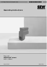
The SEW-Eurodrive MGFAT1-DSM-C/PE is a top-of-the-line motor controller with advanced features. For complete guidance on operating this product, refer to the Operating Instructions Manual available for free download from 88.208.23.73:8080. This comprehensive manual will provide you with all the information you need to utilize its capabilities effectively.
Page 2: ...SEW EURODRIVE Driving the world...
Page 123: ......


