background image

LoRa Communication Gateway
User Manual

Applied to:
SC2-A470M1
SC2-A868M1
SC2-A915M1
SC2-B470M1
SC2-B868M1
SC2-B915M1
SC2-A470M2
SC2-B470M2

Summary of Contents for SC2-A470M1

Page 1: ...LoRa Communication Gateway User Manual Applied to SC2 A470M1 SC2 A868M1 SC2 A915M1 SC2 B470M1 SC2 B868M1 SC2 B915M1 SC2 A470M2 SC2 B470M2 ...

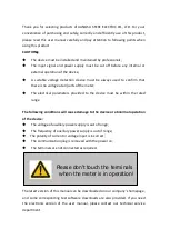
Page 2: ...meter The electrical parameters provided to the device must be within the rated range The following conditions will cause damage to the device or abnormal operation of the device The voltage of auxiliary power supply is out of range The frequency of auxiliary power supply is out of range The polarity of current or voltage input is incorrect The communication plug is removed with the power on The t...

Page 3: ...ct parameters 5 3 3 Interface description 6 3 4 Working indicator 6 3 5 Dimensions 7 4 Application Cases 7 4 1 Features of LoRa Solution 7 4 2 Modbus data acquisition 7 5 Product function 9 5 1 Working mode selection 9 5 2 Parameter configuration 9 5 3 Signal strength indicator 11 5 4 Firmware upgrade 11 ...

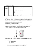
Page 4: ...This chapter mainly introduces the transparent transmission test guidance of the product The related software involved is as follows SmartHMI Sfere general purpose small gateway configuration tool which integrates configuration debugging and monitoring is simple and easy to use If you have purchased SC2 there will be the following accessories Three conditions must be met for the sender and receive...

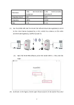
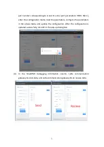
Page 5: ... the USB to 485 tool to connect the LoRa communication gateway A and B to the serial device replaced by a PC install the antenna on the LoRa communication gateway and then power on 2 Open the SmartHMI software select the model of DTU SC2 and click Login 3 As shown in the figure click to open the serial port in turn select the serial ...

Page 6: ... the parameters configure the parameters in the above table and update the configuration After the configuration is updated successfully click OK in the pop up dialog box 4 In the SmartHMI debugging information column LoRa communication gateway A sends data and LoRa communication gateway B can receive data ...

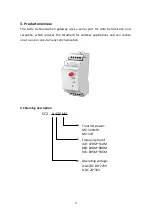
Page 7: ... and reception which reduces the threshold for wireless applications and can realize one to one or one to many communication 3 1 Naming description SC2 A 470 M1 Transmit power M1 100mW M2 1W Frequency band 470 470M 510M 868 848M 888M 915 895M 935M Operating voltage A AC DC 80 270V B DC 20 36V ...

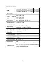
Page 8: ...are parameters RS485 interface Baud rate 1200bps 9600bps Data format N 8 1 O 8 1 N 8 2 E 8 1 Operating voltage AC DC 80 270V or DC 20 36V Operating temperature 25 C 70 C Storage temperature 40 C 85 C Relative humidity 95 RH no condensation Working altitude 2000m Anti pollution grade No corrosive gas Protection level IP20 Insulation Signal power output terminal to case resistance 100MΩ Withstand vo...

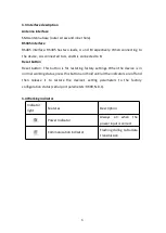
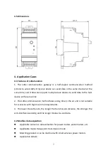
Page 9: ... This button is for restoring factory settings When the device is in normal working status press this button and hold until all the indicators are off and then release it to restore the device s setting parameters to the factory configuration status serial port parameters 9600 N 8 1 3 4 Working indicator Indicator light Features Description Power Indicator Always on when the power input is correct...

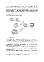
Page 10: ... same time 2 The LoRa communication method takes a long time in the air and is not suitable for scenarios with high real time requirements 3 The lower the LoRa rate the longer the transmission distance the stronger the anti interference ability and the longer it takes to send data 4 2 Modbus data acquisition Applicable scenarios data collection for power meters water meters etc Applicable mode tra...

Page 11: ... walls you can try to select the rate of 3 1K and 5 5K When there is more penetration of solid walls you can try to use the rate of 0 3K for testing Obstacles will shorten the communication distance which is subject to the actual test 2 This data acquisition scheme is also suitable for DL T 645 and other similar Modbus protocol acquisition methods 3 In order to avoid signal interference the data o...

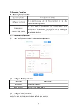
Page 12: ...n mode It can realize one to one or one to many data transparent transmission playing the role of serial port wireless extension 5 2 Parameter configuration 1 Enter configuration mode click to read configuration 2 Configure RS485 parameters Parameter Description Baud rate 1200bps 9600bps Data Format N 8 1 E 8 1 O 8 1 N 8 2 3 Configure LoRa parameters LoRa has two configuration modes Default and cu...

Page 13: ...ary to ensure that the frequency spread spectrum bandwidth and coding rate of each communication gateway is consistent Mode Parameter Default Frequency band Frequency Rate Transmit power Custom Frequency Transmit power Spread spectrum Bandwidth Code rate 4 Click to update configuration 5 A prompt box will pop up when the configuration is updated successfully click OK ...

Page 14: ...hat both parties can communicate 2 The LoRa communication gateway A enters the configuration mode 3 LoRa Communication Gateway B uses serial port tool to send data periodically Click Read Parameters on SmartHMI to view the signal strength the larger the value is the more stable it is Note It is recommended to use the signal strength within the range of 120 0 5 4 Firmware upgrade 1 Click Firmware u...

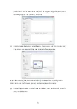
Page 15: ...select Sfere as the protocol and click to enter IAP The entry is successful and the power indicator flashes quickly Note After entering IAP the communication parameters must be configured as 9600 N 8 1 and the firmware program can be downloaded normally 4 Click the Open button to add the BIN file which is to be downloaded and then click the Send button ...

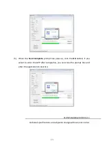
Page 16: ...ox pops up click the OK button If you select to enter the APP after completion you can close the prompt box and enter the application to execute F10505540004 20IH0 V1 0 1 Technical specifications are subject to change without prior notice ...

Reviews: