background image

1

20LK31M
20LK61M

COLOR TELEVISION

Chassis No. SN-70A

In the interests of user-safety (Required by safety regulations in some countries) the set should be restored to its
original condition and only parts identical to those specified should be used.

S80G420LK31M/

»

 ELECTRICAL SPECIFICATIONS ......................................................................................................... 1

»

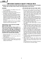
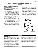
 IMPORTANT SERVICE SAFETY PRECAUTION ................................................................................ 2

»

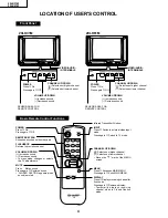
 LOCATION OF USER'S CONTROL ..................................................................................................... 4

»

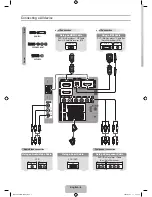
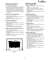
 INSTALLATION AND SERVICE INSTRUCTIONS ............................................................................... 5

»

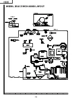
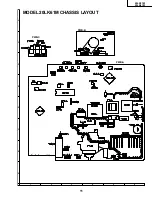
 CHASSIS LAYOUT ............................................................................................................................. 10

»

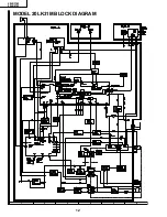
 BLOCK DIAGRAM .............................................................................................................................. 12

»

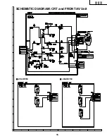
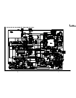
 SCHEMATIC DIAGRAMS ................................................................................................................... 14

»

 PRINTED WIRING BOARD ASSEMBLIES ........................................................................................ 21

»

 REPLACEMENT PARTS LIST ........................................................................................................... 24

»

 PACKING OF THE SET ...................................................................................................................... 31

Page

CONTENTS

ELECTRICAL SPECIFICATIONS

Specifications are subject to change without
prior notice.

SERVICE MANUAL

20LK31M
20LK61M

SHARP CORPORATION

MODELS

20LK61M

20LK31M

POWER INPUT ........................................ 110-220 V AC 50/60 Hz
POWER RATING

20LK31M ............................................................................ 88 W
20LK61M ............................................................................ 98 W

PICTURE SIZE .......................................... 1,194cm

2

 (185sq inch)

CONVERGENCE ............................................................ Magnetic
SWEEP DEFLECTION .................................................... Magnetic
FOCUS .............................................. Hi-Bi-Potential Electrostatic
INTERMEDIATE FREQUENCIES

Picture IF Carrier Frequency .................................... 45.75 MHz
Sound IF Carrier Frequency ..................................... 41.25 MHz
Color Sub-Carrier Frequency ................................... 42.17 MHz

 (Nominal)

AUDIO POWER

OUTPUT RATING
  20LK31M ........................................... 1.5W (at 10% distortion)
  20LK61M ........................................... 3.0W (at 10% distortion)

SPEAKER

SIZE ........................................................................ 9 cm 

×

 5 cm

VOICE COIL IMPEDANCE
    20LK31M ................................................... 16 ohm at 400 Hz
    20LK61M ................................................... 32 ohm at 400 Hz

ANTENNA INPUT IMPEDANCE

VHF/UHF ................................................... 75 ohm Unbalanced

TUNING RANGES

VHF-Channels ............................................................. 2 thru 13
UHF-Channels ........................................................... 14 thru 69
CATV Channels ......................................................... 1 thru 125

LK

LK

Summary of Contents for 20LK31M

Page 1: ...ications are subject to change without prior notice SERVICE MANUAL 20LK31M 20LK61M SHARP CORPORATION MODELS 20LK61M 20LK31M POWER INPUT 110 220 V AC 50 60 Hz POWER RATING 20LK31M 88 W 20LK61M 98 W PICTURE SIZE 1 194cm2 185sq inch CONVERGENCE Magnetic SWEEP DEFLECTION Magnetic FOCUS Hi Bi Potential Electrostatic INTERMEDIATE FREQUENCIES Picture IF Carrier Frequency 45 75 MHz Sound IF Carrier Freque...

Page 2: ...ge does not exceed the specified value and that it is regulating correctly 5 Do not use a picture tube other than that specified or make unrecommended circuit modifications to the high voltage circuitry 6 When trouble shooting and taking test measurements on a receiver with excessive high voltage avoid being unnecessarily close to the receiver Do not operate the receiver longer than is necessary t...

Page 3: ...rks mechanical insulators and etc 3 To be sure that no shock hazard exists check for leakage current in the following manner Plug the AC cord directly into a 120 volt AC outlet Do not use an isolation transformer for this test Using two clip leads connect a 1 5k ohm 10 watt resistor paralleled by a 0 15mF capacitor in series with all exposed metal cabinet parts and a known earth ground such as ele...

Page 4: ...n Press again Off REMOTE KEYPAD Accesses any channel from keypad FLASHBACK Returns to previous channel VOLUME UP DOWN Increases sound Decreases sound In menu mode changes or selects the TV adjustments MUTE Press Mutes sound Press again Restores sound CLOSED CAPTION appears when sound is muted LK 20LK61M 20LK31M LK VIDEO AUDIO IN TERMINALS CHANNEL UP DOWN Selects next higher channel Selects next lo...

Page 5: ...operation of the horizontal oscillator does not stop in step 5 the circuit must be repaired before the set is returned to the customer HIGH VOLTAGE CHECK High voltage is not adjustable but must be checked to verify that the receiver is operating within safe and efficient design limitations as specified checks should be as follows 1 Connect an accurate high voltage meter between ground and anode of...

Page 6: ...ormal mode Use the reset function in the video adjustment menu to ensure customer control are in their proper reset position 2 Service number selection In the service mode you will see the window screen as window 1 There are 3 adjustment categories 2DEF 3SIGNAL 4FIX VALUE as show in Figure A Press CH UP DOWN button for selection and enter by VOL UP or VOL DOWN Press CH UP DOWN button to select the...

Page 7: ...cuit S04 SUB BIAS 00 FF 40 Must be 30 S05 R BIAS 00 FF 00 S06 G BIAS 00 FF 00 S07 B BIAS 00 7F 00 S08 R DRIVE 00 7F 40 S09 B DRIVE 00 7F 40 S10 CONTRAST 00 7F 5A S11 TINT 00 7F 40 S12 COLOR 00 7F 40 S13 BRIGHTNESS 00 7F 40 SERVICE POSITION ADJUST ITEM DATA RANGE INITIAL VALUE ADJUSTMENT CONTENTS Holding down both the Vol up Ch down buttons on the TV set at service mode for more than 2 seconds will...

Page 8: ...el 2 Enter the service mode signal category and select the service adjustment S01 3 Set the data value to point where no noise or beat appears 4 Select another channel to confirm that no noise or beat appears Note You have to exit the service mode first to select another channel Video Level TV Det Video Level Adjustment 1 Receive a good local channel 2 Enter the service mode signal category and se...

Page 9: ... reading of the rms voltmeter is minimum 5 Receive the following composite stereo signal 2 Stereo signal 30 modulation left channel only noise reduction on 3kHz 6 Enter the service mode and select the service adjustment M05 7 Adjust the data until the AC voltage reading of the rms voltmeter is minimum 8 Take the above steps 1 thru 7 again for fine adjustment Vertical Size V Linearity and V S Corre...

Page 10: ...10 20LK31M 20LK61M 6 5 4 3 2 1 A B C D E F G H MODEL 20LK31M CHASSIS LAYOUT PWB A PWB B PWB C ...

Page 11: ...11 20LK31M 20LK61M 6 5 4 3 2 1 A B C D E F G H MODEL 20LK61M CHASSIS LAYOUT PWB A PWB B PWB C ...

Page 12: ...12 20LK31M 20LK61M 6 5 4 3 2 1 A B C D E F G H MODEL 20LK31M BLOCK DIAGRAM ...

Page 13: ...13 20LK31M 20LK61M 6 5 4 3 2 1 A B C D E F G H MODEL 20LK61M BLOCK DIAGRAM ...

Page 14: ... for normal picture unless otherwise indicated 2 All voltages measured with 1000µ V B W or Color signal WAVEFORM MEASUREMENT CONDITIONS 1 Photographs taken on a standard gated color bar signal the tint setting adjusted for proper color The wave shapes at the red green and blue cathodes of the picture tube depend on the tint color level and picture control 2 indicates waveform check points See char...

Page 15: ...15 20LK31M 20LK61M 6 5 4 3 2 1 A B C D E F G H SCHEMATIC DIAGRAM CRT and FRONT AV Unit Ë 20LK61M Ë 20LK31M ...

Page 16: ...17 20LK31M 20LK61M 16 12 11 10 9 8 7 6 5 4 3 2 1 A B C D E F G H MODEL 20LK31M SCHEMATIC DIAGRAM MAIN Unit ...

Page 17: ...19 20LK31M 20LK61M 18 12 11 10 9 8 7 6 5 4 3 2 1 A B C D E F G H MODEL 20LK61M SCHEMATIC DIAGRAM MAIN 1 Unit ...

Page 18: ...20 20LK31M 20LK61M 6 5 4 3 2 1 A B C D E F G H MODEL 20LK61M SCHEMATIC DIAGRAM MAIN 2 Unit ...

Page 19: ...21 20LK31M 20LK61M 6 5 4 3 2 1 A B C D E F G H PWB C FRONT AV Unit Wiring Side PWB B CRT Unit Wiring Side PRINTED WIRING BOARD ASSEMBLIES ...

Page 20: ...22 20LK31M 20LK61M 6 5 4 3 2 1 A B C D E F G H PWB A MAIN Unit Wiring Side ...

Page 21: ...23 20LK31M 20LK61M 6 5 4 3 2 1 A B C D E F G H PWB A MAIN Unit Component Side ...

Page 22: ...A78S05P 1 J KA78S05P AD or VHiTA7805S 1 å IC201 RH iX3354CEZZ J LA76843 AT IC351 VHiAN7511 1 J AN7511 AK å IC501 VHiLA7840 1 J LA7840 AR å IC701 VHiSTR301301E J STR30130 AP å IC751 VHiKA7809Pi 1 R KA7809PI AE å IC761 VHiKA7812Pi 1 R KA7812PI AE or VHiTA7812Si 1 IC771 VHiKA7805Pi 1 R KA7805PI AE or VHiTA7805S 1 IC2001 RH iX3355CEN2 J TMPA8700CPF166 AU IC2040 VHiPST994C 1 J PST994C AD IC2101 VHiBR24...

Page 23: ...EL AB C210 VCEA0A1HW474M J 0 47 50V EL AB C211 VCKYCY1HB102K J 1000p 50V Ceramic AA C212 VCEA0A1HW474M J 0 47 50V EL AB C220 VCKYCY1CB104K J 0 1 16V Ceramic AB C301 VCCCCY1HH470J J 47p 50V Ceramic AA C302 VCKYCY1HB102K J 1000p 50V Ceramic AA C303 VCKYPA1HB103K J 0 01 50V Ceramic AA 20LK31M C304 VCCCCY1HH470J J 47p 50V Ceramic AA C305 VCKYCY1HB103K J 0 01 50V Ceramic AA C354 VCEA0A1HW225M J 2 2 50V...

Page 24: ...4 VRS CY1JF822J J 8 2k 1 16W M Ox AA 20LK61M R355 VRD RA2BE223J J 22k 1 8W Carbon AA R357 VRD RA2BE103J J 10k 1 8W Carbon AA 20LK61M R357 VRD RA2BE822J J 8 2k 1 8W Carbon AA 20LK31M R401 VRS CY1JF470J J 47 1 16W M Ox AA R402 VRS CY1JF470J J 47 1 16W M Ox AA R403 VRS CY1JF470J J 47 1 16W M Ox AA R404 VRD RA2BE102J J 1 0k 1 8W Carbon AA R410 VRS CY1JF471J J 470 1 16W M Ox AA R411 VRS CY1JF684J J 680...

Page 25: ...BE562J J 5 6k 1 8W Carbon AA R754 VRS CY1JF471J J 470 1 16W M Ox AA å R755 VRS VV3LB270J J 27 3 0W M Ox AB R757 VRD RA2BE472J J 4 7k 1 8W Carbon AA å R758 VRS SV2HC100J J 10 1 2W M Ox AA R763 VRD RA2EE473J J 47k 1 4W Carbon AA R771 VRS VV3DB330J J 33 2W M Ox AA R801 VRD RM2HD470J J 47 1 2W Carbon AA R807 VRS CY1JF272J J 2 7k 1 16W M Ox AA R808 VRS CY1JF272J J 2 7k 1 16W M Ox AA R809 VRS CY1JF223J ...

Page 26: ...5 VRD RA2BE223J J 22k 1 8W Carbon AA 20LK61M R3377 VRD RA2BE103J J 10k 1 8W Carbon AA 20LK61M SWITCHES S2501 QSW K0202PEZZ R Power AC or QSW K0079GEZZ S2502 QSW K0202PEZZ R VOL Down AC or QSW K0079GEZZ S2503 QSW K0202PEZZ R VOL UP AC or QSW K0079GEZZ S2504 QSW K0202PEZZ R CH Down AC or QSW K0079GEZZ S2505 QSW K0202PEZZ R CH UP AC or QSW K0079GEZZ MISCELLANEOUS PARTS å RY701 RRLYU0041CEZZ J Relay A...

Page 27: ... 1 8W Carbon AA å R857 VRS VV3AB123J J 12k 1W M Ox AA R858 VRD RM2HD332J J 3 3k 1 2W Carbon AA R859 VRD RA2BE470J J 47 1 8W Carbon AA R860 VRD RA2BE121J J 120 1 8W Carbon AA R861 VRD RA2BE181J J 180 1 8W Carbon AA å R865 VRS VV3AB123J J 12k 1W M Ox AA R866 VRD RM2HD332J J 3 3k 1 2W Carbon AA R868 VRD RA2BE181J J 180 1 8W Carbon AA R869 VRD RA2BE121J J 120 1 8W Carbon AA å R873 VRS VV3AB123J J 12k ...

Page 28: ...P16000 J Screw AA XTASD40P20000 J Screw AA SPAKC0134GJZZ Packing Case 20LK31M SPAKC0135GJZZ Packing Case 20LK61M SPAKP0102GJZZ Polyethylene Foam Wrap SPAKX0002GJZZ Buffer Material SSAKA0101GJZZ Polyethylene Bag 1 CCABA0110WEH0 X Front Cabinet Ass y BB 20LK31M 1 CCABA0111WEH0 X Front Cabinet Ass y BA 20LK61M 1 1 Not Available Front Cabinet 1 2 GCOVA0002GJSA X Cover for R C AL 1 3 HBDGB0019PESB R Ba...

Page 29: ...n Code 31 20LK31M 20LK61M PACKING OF THE SET REAR Use tapes to fix the packing case Packing Case FRONT Buffer Material Polyethylene Foam Wrap Polyethylene Bag MARK Not Replacement Items Operation Manual Infrared R C Unit Rod Antenna Antenna Adapter Batteries ...

Page 30: ...ication may be reproduced stored in a retrieval system or transmitted in any form or by any means electronic mechanical photocopying recording or otherwise without prior written permission of the publisher SHARP CORPORATION AV Systems Group Quality Reliability Control Center Yaita Tochigi 329 2193 Japan D SEMEX P SEMEX TQ0967 S Aug 2000 Printed in Japan MI KG ...

Reviews: