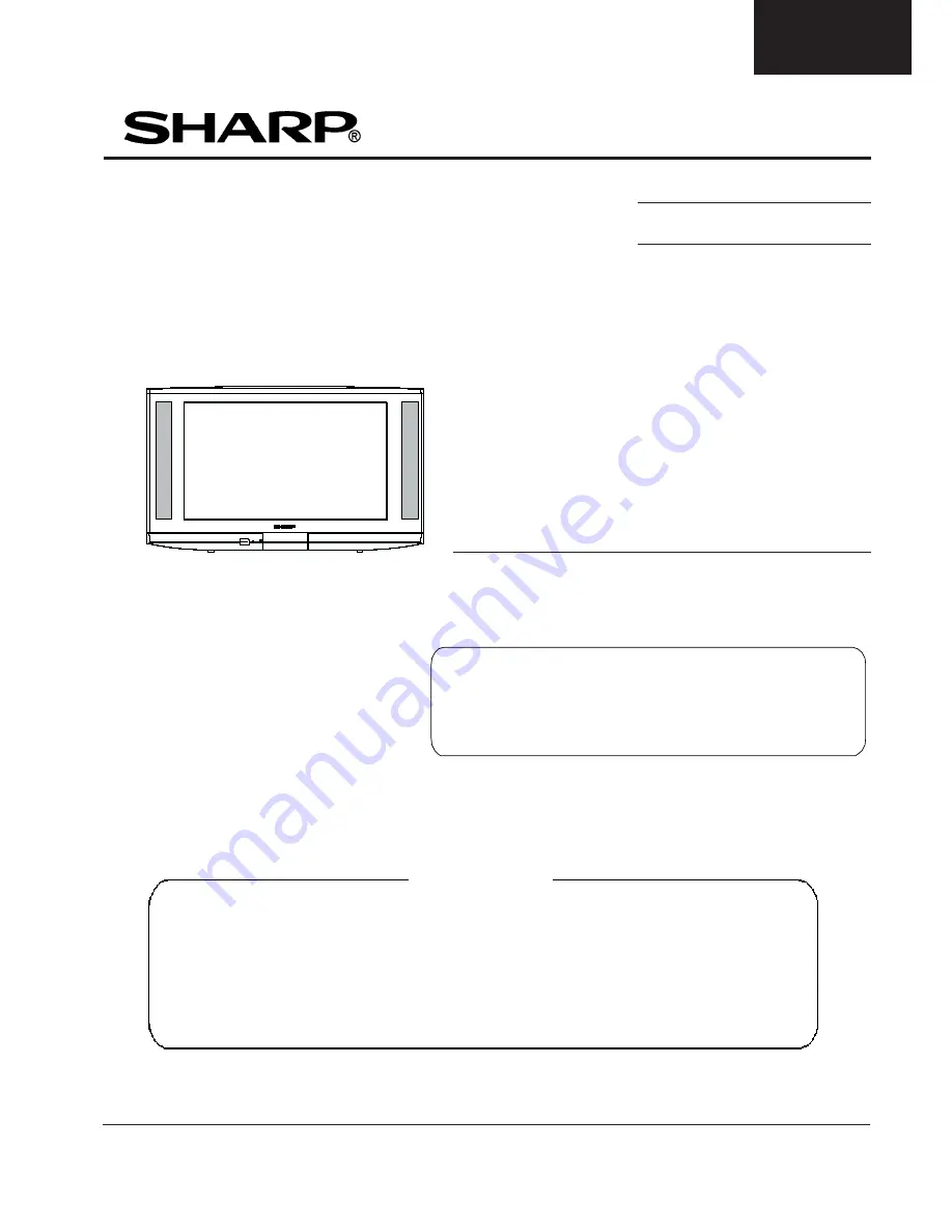
background image

1

28JF-73E

This document has been published to
 be used for after sales service only.

In the interests of user safety (required by safety
regulations in some countries) the set should restored
to its original condition and only parts identical to
those specified should be used.

CONTENTS

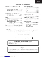
ELECTRICAL SPECIFICATIONS ................... 3
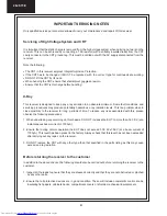
IMPORTANT SERVICING NOTES ................. 4
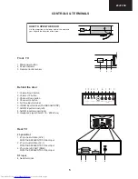
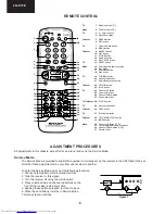
CONTROLS & TERMINALS ........................... 5
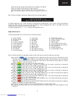
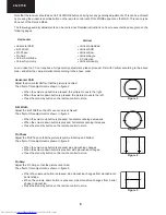
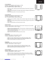
ADJUSTMENT PROCEDURES ...................... 6
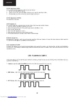
LED FLASHING CODES ............................... 12
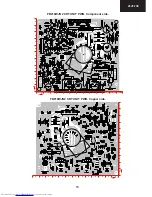
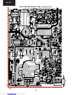
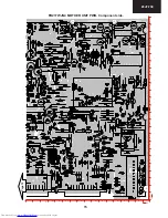
PRINTED WIRING BOARDS ........................ 13
CHASSIS LAYOUT ......................................... 20

ICs ADDITIONAL INFORMATION .................. 22
SCHEMATIC DIAGRAMS ............................... 32
TROUBLESHOOTING TABLES ..................... 46
PARTS LISTING ............................................. 49
PACKING OF THE SET & ACCESSORIES ... 58
SOURCE OF DOCUMENTATION .................. 59

SHARP  CORPORATION

MODEL 

28JF-73E

ES

 PAL 

B/G, I 

/ SECAM

 L/L’, B/G, D/K  

SYSTEM COLOUR TELEVISION

SE

00

28JF73E00

SERVICE MANUAL


  Issued: 2

4

th 

 Sept. 2002

  GA-20

 CHASSIS

Summary of Contents for 28JF-73E

Page 1: ...TENTS ELECTRICAL SPECIFICATIONS 3 IMPORTANT SERVICING NOTES 4 CONTROLS TERMINALS 5 ADJUSTMENT PROCEDURES 6 LED FLASHING CODES 12 PRINTED WIRING BOARDS 13 CHASSIS LAYOUT 20 ICs ADDITIONAL INFORMATION 22 SCHEMATIC DIAGRAMS 32 TROUBLESHOOTING TABLES 46 PARTS LISTING 49 PACKING OF THE SET ACCESSORIES 58 SOURCE OF DOCUMENTATION 59 SHARP CORPORATION MODEL 28JF 73EES PAL B G I SECAML L B G D K SYSTEM COL...

Page 2: ...f only part number changes are required just change part number directly the part number in the Parts Listing Section If you need more information please refer to the Technical Report Bulletin SERVICE MANUAL UPDATE LOG SHEET Part No Technical Report No Technical Bulletin No Cause Solution Page No Application Data Serial No ...

Page 3: ...ethod IEC60107 77W Stand by Operation 3W Audio Power Output Rating MPO Impedance Internal Left Speaker 10W 7Ω Internal Right Speaker 10W 7Ω Speakers Left Right 13 x 6cm Convergence Maximum Misconvergence Static Centre between any two colours 0 08 cm Dynamic after static equals zero Within 10cm 4 circle 0 12cm 10 25cm 4 10 circle 0 20 cm Everywhere else 0 28 cm Focus High Bi Potential Electrostatic...

Page 4: ... x ray radiation levels This is a problem when in close proximity to the receiver for long periods of time To reduce any risks associated with this please observe the following precautions 1 When undertaking any servicing on this chassis DO NOT increase the EHT to more than 32 5 KV at a instantaneous beam current of 1500µA 2 Ensure that during normal operation the EHT does not exceed 30 0 KV 1 5KV...

Page 5: ...5 28JF 73E 1 2 3 HOW TO OPEN THE DOOR Lift the projection at the lower right of the door with your finger in the direction of the arrow 8 4 2 3 1 0 1 2 3 4 a 55 6 6 78 6 CONTROLS TERMINALS ...

Page 6: ...4 5 TV 1 Stand by button TV Video 2 Power button VCR TV 3 0 9 digit buttons 4 Flash back button Teletext 5 GREEN button 6 RED button TV 7 Volume DOWN button 8 MENU button Teletext 9 REVEAL button 10 LIST button 11 STORE button 12 CANCEL button 13 HALF PAGE button TV 14 RESET button Video 15 Rewind picture search reverse 16 Play button 17 Pause Still button 18 Stop button TV 19 TV VIDEO button 20 C...

Page 7: ...reen button twice to enter FACTORY BALANCE level Use volume control keys to change the setting The original value will be recovered after resetting the TV set Press the Green button three times to enter FACTORY BASS level Use volume control keys to change the setting The original value will be recovered after resetting the TV set Press the Green button four times to enter FACTORY TREBLE level Use ...

Page 8: ...n button is pressed side pincushion changes Press the stand by button on the remote control to store Pin Amp Adjust the Pin Amp so that the picture is centred The effect of this adjustment is shown in figure 5 When the volume up button is pressed side pincushion changes from pincushion to barrel shape When the volume down button is pressed side pincushion changes from barrel shape to pincushion Pr...

Page 9: ...nning decreases and the lower picture scanning increases When the volume down button is pressed the upper picture scanning increases and the lower picture scanning decreases Press the stand by button on the remote control to store Vertical Angle Adjust the Vertical Angle so that the picture is centred The effect of this adjustment is shown in figure 9 When the volume up button is pressed the verti...

Page 10: ...crease press volume up button and to decrease press volume down button RED CUT OFF alter X coordinate GREEN CUT OFF alter Y coordinate BLUE CUT OFF alter X and Y coordinate 3 Follow the procedure below to set the GAIN 3 1 Using brightness and contrast buttons select a luminance of 100 NITS S Correction Adjust the S Correction so that the picture symmetrical between the top centre and bottom The ef...

Page 11: ...ettings to achieve good tracking Note The data to be adjusted is contained at the bottom right corner of the picture See Figure 15 Changing NVM Data To change the data contained within the Non Volatile Memory it is necessary to first select the page the data is stored in then the position and finally to change the data itself The procedure below outlines this process 1 Press the channel up down bu...

Page 12: ...otation Inspection No adjustment required Just to check the proper working of this user feature It cannot be memorized and after reset the TV the picture will appear normalized as other features Auto Installation On Off To return the receiver to the original Auto Installation mode using the volume up or down button set the Auto Installation On Off to On This setting is automatically stored and whe...

Page 13: ...3 28JF 73E FB218WJN2 CRT UNIT PWB Component side FB218WJN2 CRT UNIT PWB Copper side 11 1 2 3 4 5 6 7 8 9 10 Y X 0 10 11 12 13 1 2 3 4 5 6 7 8 9 Y X 11 1 2 3 4 5 6 7 8 9 10 0 10 9 8 7 6 5 4 3 2 1 13 12 11 ...

Page 14: ...14 28JF 73E 22 23 24 25 17 18 19 20 21 11 12 13 14 15 16 1 2 3 4 5 6 7 8 9 10 Y X 0 10 11 12 13 14 15 16 17 1 2 3 4 5 6 7 8 9 Page 15 FB217WJN4 MOTHER UNIT PWB Component side ...

Page 15: ...15 28JF 73E FB217WJN4 MOTHER UNIT PWB Component side Page 14 29 30 31 32 33 20 21 22 23 24 25 26 27 28 17 18 19 Y X 22 23 24 25 17 18 19 20 21 11 12 13 14 15 16 1 2 3 4 5 6 7 8 9 10 16 ...

Reviews: