background image

1

32R-S60

SHARP CORPORATION

This document has been published to be used for after
sales service only.
The contents are subject to change without notice.

In the interests of user-safety (Required by safety regulations in some countries ) the set should be restored to its
original condition and only parts identical to those specified should be used.

S81Z732R-S60/

COLOR TELEVISION

Chassis No. MS-B

Page

»

 ELECTRICAL SPECIFICATIONS ......................................................................................................... 1

»

 IMPORTANT SERVICE SAFETY PRECAUTION ................................................................................. 2

»

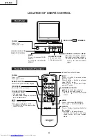
 LOCATION OF USER'S CONTROL ..................................................................................................... 4

»

 INSTALLATION AND SERVICE INSTRUCTIONS ................................................................................ 5

»

 SERVICE ADJUSTMENT ..................................................................................................................... 9

»

 CHASSIS LAYOUT ............................................................................................................................. 12

»

 BLOCK DIAGRAM .............................................................................................................................. 13

»

 SCHEMATIC DIAGRAMS ................................................................................................................... 14

»

 PRINTED WIRING BOARD ASSEMBLIES ........................................................................................ 23

»

 REPLACEMENT PARTS LIST ............................................................................................................ 27

»

 PACKING OF THE SET ...................................................................................................................... 36

CONTENTS

SPEAKER

SIZE ................................................. 12 cm 

× 

6 cm Oval (2 pcs.)

VOICE COIL IMPEDANCE ............................... 8 ohm at 400 Hz

ANTENNA INPUT IMPEDANCE

VHF/UHF ..................................................... 75 ohm Unbalanced

TUNING RANGES

VHF-Channels ............................................................... 2 thru 13

UHF-Channels ............................................................ 14 thru 69

CATV Channels ........................................................... 1 thru 125

(EIA, Channel Plan U.S.A.)

POWER INPUT ..................................................... 120V  AC 60 Hz

POWER RATING .................................................................. 152W

PICTURE SIZE ........................................... 3,073cm

(476sq inch)

CONVERGENCE ............................................................. Magnetic

SWEEP DEFLECTION .................................................... Magnetic

FOCUS ............................................... Hi-Bi-Potential Electrostatic

INTERMEDIATE FREQUENCIES

Picture IF Carrier Frequency ..................................... 45.75 MHz

Sound IF Carrier Frequency ...................................... 41.25 MHz

Color Sub-Carrier Frequency .................................... 42.17 MHz

 (Nominal)

AUDIO POWER

OUTPUT RATING .............. 3.0W + 3.0W (at 10% distortion and

Dual CH Operate)

Specifications are subject to change without
prior notice.

ELECTRICAL SPECIFICATIONS

MODEL

SERVICE MANUAL

32R-S60

Summary of Contents for 32R-S60

Page 1: ...NTED WIRING BOARD ASSEMBLIES 23 REPLACEMENT PARTS LIST 27 PACKING OF THE SET 36 CONTENTS SPEAKER SIZE 12 cm 6 cm Oval 2 pcs VOICE COIL IMPEDANCE 8 ohm at 400 Hz ANTENNA INPUT IMPEDANCE VHF UHF 75 ohm Unbalanced TUNING RANGES VHF Channels 2 thru 13 UHF Channels 14 thru 69 CATV Channels 1 thru 125 EIA Channel Plan U S A POWER INPUT 120V AC 60 Hz POWER RATING 152W PICTURE SIZE 3 073cm2 476sq inch CON...

Page 2: ...igh voltage with a meter to be certain that the high voltage does not exceed the specified value and that it is regulating correctly 5 Do not use a picture tube other than that specified or make unrecommended circuit modifications to the high voltage circuitry 6 When trouble shooting and taking test measurements on a receiver with excessive high voltage avoid being unnecessarily close to the recei...

Page 3: ...ment covers or shields isolation resistor capacity networks mechanical insulators etc 3 To be sure that no shock hazard exists check for leakage current in the following manner Plug the AC cord directly into a 120 volt AC outlet Do not use an isolation transformer for this test Using two clip leads connect a 1 5k ohm 10 watt resistor paralleled by a 0 15µF capacitor in series with all exposed meta...

Page 4: ... to the original TV mode CHANNEL UP DOWN Selects next higher channel Selects next lower channel Moves the mark of the MENU screen MENU Press Accesses MAIN MENU Press again Exits MAIN MENU DISPLAY Press Displays receiving channel for four seconds Press again Removes display Temporarily displays receiving channel when in Closed Caption mode Basic Remote Control Functions POWER Press On Press again O...

Page 5: ...izontal oscillator does not stop in step 5 the circuit must be repaired before the set is returned to the customer HIGH VOLTAGE CHECK High voltage is not adjustable but must be checked to verify that the receiver is operating within safe and efficient design limitations as specified checks should be as follows 1 Connect an accurate high voltage meter between ground and anode of picture tube 2 Oper...

Page 6: ...on in the video adjustment menu to ensure customer controls are in their proper reset position 2 Service number selection Once in the service mode press the Ch up or Ch down button on the remote controller or at the set The service adjustment number will vary in increments of one from V01 to P08 Select the item you wish to adjust 3 Data number selection Press theVol up orVol down button to adjust ...

Page 7: ... 63 00h 3Fh Must be set to 2A V32 Y DL 02 0 7 00h 07h Must be set to 02 V33 Y DL INPUT 01 0 7 00h 07h Must be set to 01 V34 VSM GAIN 07 0 7 00h 07h Must be set to 07 V35 N COMB 01 0 1 Must be set to 01 V36 BPF TOF INPUT 00 0 1 Must be set to 00 V37 CORING 00 0 1 Must be set to 00 V38 VSM PHASE 00 0 1 Must be set to 00 V39 COLOR γ 00 0 1 Must be set to 00 V40 SHARP INPUT 14 0 63 00h 3Fh Must be set...

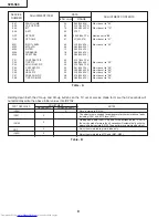
Page 8: ... 00 P07 FREE RUN PIP 0B 0 15 00h 0Fh Must be set to 0B P08 TINT PIP INPUT 24 0 63 00h 3Fh Must be set to 24 SERVICE NUMBER DATA ADJUSTMENT ITEM INITIAL VALUE RANGE ADJUSTMENT CONTENTS Table A NECESSARY UNNECESSARY ADJUSTMENT PART REPLACED IC2001 IC201 X Data is stored in IC2102 The adjustment is needed to compensate for characteristics of parts including IC201 and MTS level M01 Holding down both t...

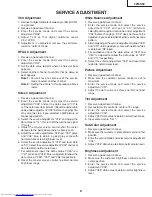
Page 9: ...ue of V46 red V47 green and V48 blue is adjusted to follow the data value of V06 V07 and V08 respectively 8 Reset the master screen control to obtain normal brightness range White Balance Adjustment 1 Receive a good local channel 2 Enter the service mode and select the service adjustment V03 and set to 00 minimum color Record original data code under adjustment V03 before changing V03 does not hav...

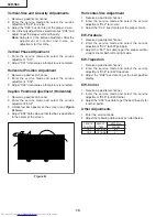
Page 10: ...xt box appears on the screen see Figure B below 4 Adjust EX2 data value so that text box is positioned in the center of the screen Other Adjustments 1 Enter the service mode 2 Adjust the following data values as listed below Figure B SERVICE POSITION ADJUST ITEM OP1 OP2 OPTION1 OPTION2 DATA Hex 32R S60 B0 31 Horizontal Size Adjustment 1 Receive a good local channel 2 Enter the service mode and sel...

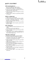
Page 11: ... stereo pilot signal to pin 14 of IC3001 Stereo pilot signal 9 4kHz 600mVrms 2 Enter the service mode and select the service adjustment M03 3 Adjust the data until OK appears in position on the screen Make sure the OK is displayed almost at the center of the data range Separation Adjustment 1 Connect the rms voltmeter to pin 39 of IC3001 2 Receive the following composite stereo signal 1 Composite ...

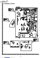
Page 12: ...12 6 5 4 3 2 1 A B C D E F G H 32R S60 CHASSIS LAYOUT ...

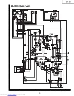
Page 13: ...13 6 5 4 3 2 1 A B C D E F G H 32R S60 BLOCK DIAGRAM ...

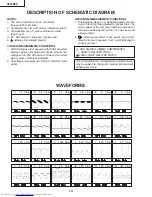
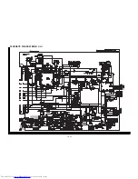
Page 14: ...NS 1 Photographs taken on a standard gated color bar signal the tint setting adjusted for proper color The wave shapes at the red green and blue cathodes of the picture tube depend on the tint color level and picture control 2 indicates waveform check points See chart waveforms are measured from point indicated to chassis ground WAVEFORMS 1 1 2 Vp p 2 2 3 Vp p 3 1 0 Vp p 4 0 5 Vp p 5 5 Vp p 6 5 Vp...

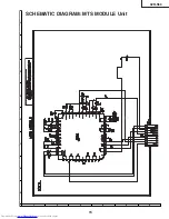
Page 15: ...15 6 5 4 3 2 1 A B C D E F G H 32R S60 SCHEMATIC DIAGRAM MTS MODULE Unit ...

Page 16: ...16 17 1 2 3 4 5 6 7 8 9 10 11 12 13 14 15 16 17 18 19 20 A B C D E F G H I J SCHEMATIC DIAGRAM MAIN 1 Unit ...

Page 17: ...18 19 1 2 3 4 5 6 7 8 9 10 11 12 13 14 15 16 17 18 19 20 A B C D E F G H I J SCHEMATIC DIAGRAM MAIN 2 Unit ...

Page 18: ...20 21 1 2 3 4 5 6 7 8 9 10 11 12 13 14 15 16 17 18 19 20 A B C D E F G H I J SCHEMATIC DIAGRAM AV Unit ...

Page 19: ...22 6 5 4 3 2 1 A B C D E F G H 32R S60 SCHEMATIC DIAGRAM CRT Unit ...

Page 20: ...23 6 5 4 3 2 1 A B C D E F G H 32R S60 PRINTED WIRING BOARD ASSEMBLIES PWB S MTS MODULE Unit Wiring Side PWB B CRT Unit Wiring Side PWB S MTS MODULE Unit Chip Parts Side ...

Page 21: ...24 6 5 4 3 2 1 A B C D E F G H 32R S60 PWB A MAIN Unit Wiring Side ...

Page 22: ...25 6 5 4 3 2 1 A B C D E F G H 32R S60 PWB A MAIN Unit Chip Parts Side ...

Page 23: ...26 6 5 4 3 2 1 A B C D E F G H 32R S60 PWB C AV Unit Chip Parts Side PWB C AV Unit Wiring Side ...

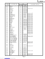
Page 24: ...TS HERE SHOWN ARE SUPPLIED AS AN ASSEMBLY BUT NOT INDEPENDENTLY å TU51 VTUVTST5UF770 J VHF Tuner AZ INTEGRATED CIRCUITS å IC201 RH iX3395CEN2 J TB1252CN AY å IC361 VHiAN5276 1 J AN5276 AR å IC501 VHiTA8427K 1 J TA8427K AL IC680 VHiKiA358P 1 X KIA358P AF å IC701 VHiTEA1507 1 J TEA1507P N1 AL å IC702 RH FX0008GEZZ J PC123FY8 AE å IC703 VHiSE125N 1 X SE125N AK IC751 VHiSTV8164 1 X STV8164 AS AM IC200...

Page 25: ...H å L701 RCiLF0313CEZZ J Coil AH or RCiLF0345CEZZ or RCiLF0273CEZZ å L702 RCiLF0313CEZZ J Coil AH or RCiLF0345CEZZ or RCiLF0273CEZZ or RCiLF0025PEZZ L705 RCiLP0179CEZZ J Coil AD L729 RCiLP0179CEZZ J Coil AD L801 VP DF100K0000 J Peaking 10µH AB L802 VP DF6R8K0000 J Peaking 6 8µH AB L2040 RCiLB0131CEZZ J Oscillation Coil AE SF201 RFiLC0405CEZZ J SAW Filter AH TRANSFORMERS T201 RCiLi0636CEZZ X If Coi...

Page 26: ...385CEZZ J 1000 16V EL AE C732 VCKYPA2HB102K J 1000p 500V Ceramic AA C735 VCEA0A1CW106M J 10 16V EL AB C736 VCEA0A1CW106M J 10 16V EL AB C737 VCEA0A1CW107M J 100 16V EL AC C738 VCFPVC3CA722H J 7200p 1 6kV M Poly AF C740 VCEA0A1EW476M J 47 25V EL AB C741 VCKYPA2HB102K J 1000p 500V Ceramic AA C742 VCKYPA2HB102K J 1000p 500V Ceramic AA C744 VCEA0A0JW107M J 100 6 3V EL AB C756 VCEA0A1CW476M J 47 16V EL...

Page 27: ...WB A DUNTKA526WEC0 MAIN UNIT R364 VRS CY1JF561J J 560 1 16W M Ox AA R365 VRS CY1JF561J J 560 1 16W M Ox AA R367 VRN RL3DBR56J X 0 56 2W M Film AE R368 VRD RA2BE222J J 2 2k 1 8W Carbon AA R369 VRD RA2BE822J J 8 2k 1 8W Carbon AA R370 VRS CY1JF122J J 1 2k 1 16W M Ox AA R371 VRS CY1JF102J J 1 0k 1 16W M Ox AA R372 VRS CY1JF223J J 22k 1 16W M Ox AA R415 VRS CY1JF101J J 100 1 16W M Ox AA R430 VRD RA2BE...

Page 28: ... J 1 0k 1 8W Carbon AA R928 VRS CY1JF750J J 75 1 16W M Ox AA R940 VRS CY1JF221J J 220 1 16W M Ox AA R961 VRS CY1JF221J J 220 1 16W M Ox AA PWB A DUNTKA526WEC0 MAIN UNIT R962 VRS CY1JF221J J 220 1 16W M Ox AA R969 VRS CY1JF221J J 220 1 16W M Ox AA R989 VRS CY1JF750J J 75 1 16W M Ox AA R991 VRS CY1JF102J J 1 0k 1 16W M Ox AA R992 VRS CY1JF122J J 1 2k 1 16W M Ox AA R2001 VRD RA2BE562J J 5 6k 1 8W Car...

Page 29: ...k for Q701 AL RDA751 PRDAR0111GJFW X Heat Sink for IC751 AF MSPRK0034BMFW J Spring AC LHLDW1002PEZZ R Holder AB LX BZ3049GEFD J Screw AA LX BZ3100CEFD J Screw AA LX HZ3007MEFD X Screw AB INTEGRATED CIRCUITS å IC850 VHiTDA6103Q 1 J TDA6103Q N3 AL TRANSISTORS Q850 VS2SA1266 Y 1 J A1266 Y AA Q851 VS2SC3198 G 1 J C3198 G AA DIODES D853 RH EX0647GEZZ J Zener Diode 15V AA or RH EX0417GEZZ D854 VHD1SS119...

Page 30: ... AB C1912 VCEA0A1HW105M J 1 0 50V EL AB C1913 VCEA0A1HW105M J 1 0 50V EL AB C1914 VCKYCY1HB681K J 680p 50V Ceramic AA C1915 VCKYCY1HF103Z J 0 01 50V Ceramic AA C1916 VCKYCY1HF103Z J 0 01 50V Ceramic AA C1921 VCKYCY1HB681K J 680p 50V Ceramic AA C1922 VCKYCY1CF104Z J 0 1 16V Ceramic AA C1923 VCEA0A1CW107M J 100 16V EL AC C1926 VCEA0A1CW226M J 22 16V EL AB C1927 VCKYCY1HB681K J 680p 50V Ceramic AA C1...

Page 31: ...Ox AA R3001 VRS CY1JF221J J 220 1 16W M Ox AA R3002 VRS CY1JF221J J 220 1 16W M Ox AA R3003 VRS CY1JF105J J 1 0 M 1 16W M Ox AA R3004 VRS CY1JF104J J 100k 1 16W M Ox AA R3005 VRS CY1JF623J J 62k 1 16W M Ox AA R3007 VRS CY1JF332J J 3 3k 1 16W M Ox AA R3008 VRS CY1JF302J J 3 0k 1 16W M Ox AA R3010 VRS CY1JF392J J 3 9k 1 16W M Ox AA R3011 VRS CY1JF102J J 1 0k 1 16W M Ox AA R3012 VRS CY1JF102J J 1 0k ...

Page 32: ...X Screw for CRT AF LX WZ0104GJFD X CRT Washer AC TCAUH3044GJZZ X Caution Card AD TLABM0002GJZZ X Label AB SUPPLIED ACCESORRIES RRMCG1324CESA J Infrared R C AT TGAN 0001GJZZ X Guarantee Card AB TiNS 7515GJZZ X Operation Manual AG SPAKC0238GJZZ Packing Case SPAKP0110GJZZ Wrapping Paper SPAKX0128GJZZ Packing Add SSAKA0101GJZZ Polyethylene Bag TLABZ0178GJZZ Packing Case Label CABINET PARTS 1 CCABA0161...

Page 33: ...eplacement items FRONT Buffer Material Polyethylene Sheet Polyethylene Bag Operation Manual Infrared R C Unit Batteries Packing Case Label Packing Case Label REAR Use tape to fix the top side of packing case Use 12 staples to fix the bottom side of packing case PACKING OF THE SET D SEM P SEMEX TQ1232 S Oct 2001 Printed in Japan MI KD ...

Reviews: