background image

1

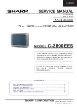
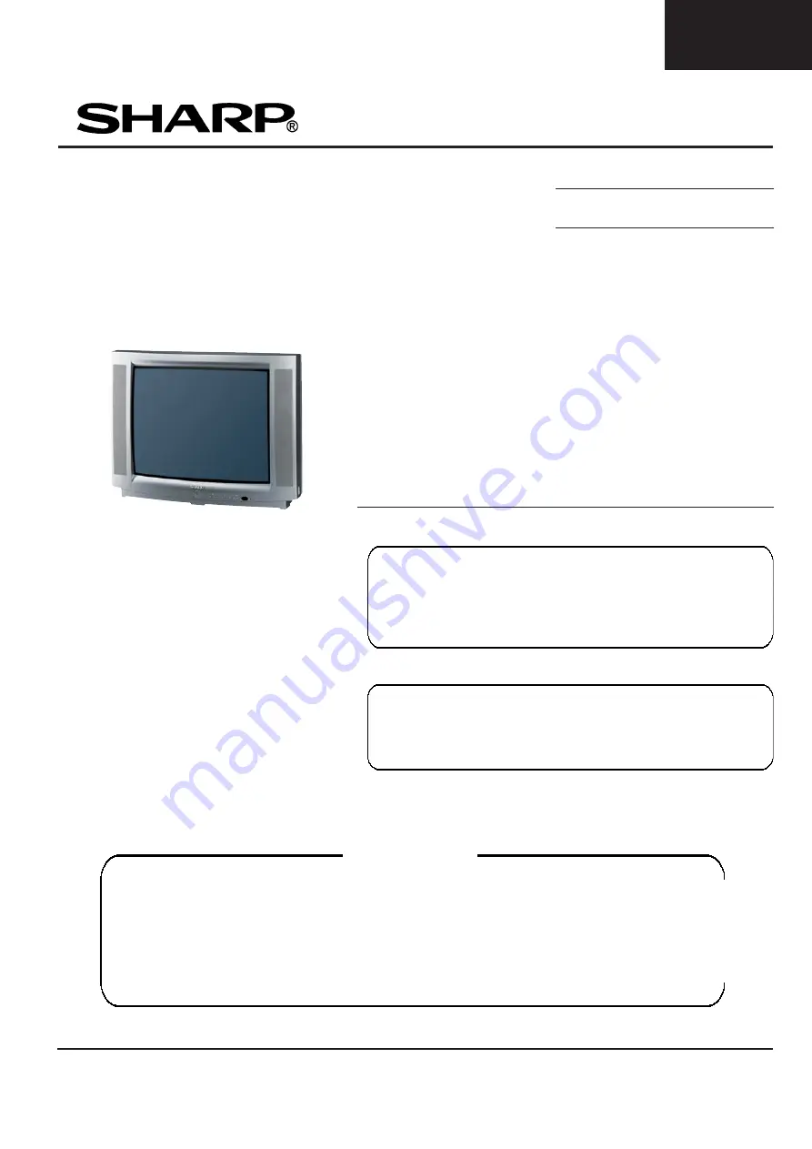
C-2890EES

SERVICE MANUAL

This document has been published to
 be used for after sales service only.

   AK- 45

 CHASSIS

In the interests of user safety (required by safety
regulations in some countries) the set should be re-
stored to its original condition and only parts identi-
cal to those specified should be used.

CONTENTS

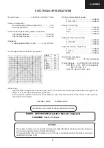
ELECTRICAL SPECIFICATIONS ........................................................................................ 3
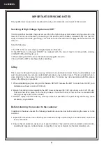
IMPORTANT SERVICING NOTES ...................................................................................... 4
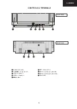
CONTROLS & TERMINALS ................................................................................................ 5
PRINTED WIRING BOARD LAYOUT ................................................................................. 7
PARTS LISTING ................................................................................................................... 8
HOW TO UPDATE THE TECHNICAL INFORMATION ...................................................... 15

SHARP  CORPORATION

    MODEL

 C-2890EES

SE

00C28

90EE00


 Issued: 28

th

 April 2004

 PAL 

B/G, I

 / SECAM 

L/L’, B/G, D/K  

SYSTEM COLOUR TELEVISION

In  order  to   service the model C-2890E

ES

, refer to

the AK-45 Chassis Service Manual
(SE

00

AK45CHA00).

Summary of Contents for C-2890EES

Page 1: ...d only parts identi cal to those specified should be used CONTENTS ELECTRICAL SPECIFICATIONS 3 IMPORTANT SERVICING NOTES 4 CONTROLS TERMINALS 5 PRINTED WIRING BOARD LAYOUT 7 PARTS LISTING 8 HOW TO UPDATE THE TECHNICAL INFORMATION 15 SHARP CORPORATION MODEL C 2890EES SE00C2890EE00 Issued 28th April 2004 PAL B G I SECAM L L B G D K SYSTEM COLOUR TELEVISION In order to service the model C 2890EES ref...

Page 2: ...If only part number changes are required just change part number directly the part number in the Parts Listing Section If you need more information please refer to the Technical Report Bulletin SERVICE MANUAL UPDATE LOG SHEET Part No Technical Report No Technical Bulletin No Cause Solution Page No Application Data Serial No ...

Page 3: ...ing Ranges 45 75MHz thru 855 25 MHz VHF IR A J S1 S41 CH Hiperband E2 E12 F2 F10 UHF I21 I69 CH E21 E69 AREA 28 29 A 0 4 BC 1 0 DE 1 0 FGHJ 1 5 KLMN 1 3 F G H J 1 3 STUV 1 0 mm Power Input 220V 240 Volts AC 50 Hz Power Consumption Normal Operation Method IEC60107 70 W Stand by Operation 4 W Audio Power Output Rating MPO Impedance Internal Left Speaker 10 W 8 Ω Internal Right Speaker 10 W 8 Ω Speak...

Page 4: ...ous x ray radiation levels This is a problem when in close proximity to the receiver for long periods of time To reduce any risks associated with this please observe the following precautions 1 When undertaking any servicing on this chassis DO NOT increase the EHT to more than 29 9 KV at a instantaneous beam current of 1000 µA 2 Ensure that during normal operation the EHT does not exceed 26 5 KV a...

Page 5: ...S TERMINALS 32 5 92 3 K 0 18 FRONT PANEL 17 7 7 REAR PANEL Speakers left right POWER Power On Off VOL Volume P Ch Program MENU Menu ANT Antenna 75 W EXT 1 Scart Socket 1 with RGB EXT 2 Scart Socket 2 with SVHS Power Cable ...

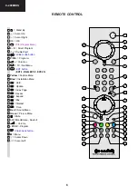
Page 6: ...ide mode button P CH Program Volume TV Quit Menu 7 EXT button EXT 1 RGB EXT 2 EXT 2S Yellow Feature Menu Blue Installation Menu Hold Update Index Page Reveal Expand Mix Teletext Time Red Sound Menu Green Picture Menu Mute I II Mono Stereo Dual I II Volume P CH Program Flash back button M Menu Cursor Down Cursor Left ...

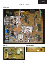
Page 7: ...7 C 2890EES CHASSIS LAYOUT Mother Unit CRT Unit Control Panel Unit ...

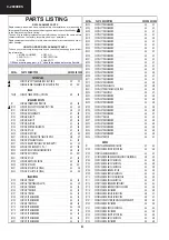
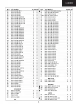
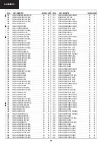
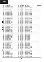
Page 8: ...48BSMD AA AC Q114 30001457 TRBC848BSMD AA AC Q200 30001457 TRBC848BSMD AA AC Q201 30001457 TRBC848BSMD AA AC PICTURE TUBE REFNo PARTS DESCRIPTION SNCODE EXCODE Q202 30001457 TRBC848BSMD AA AC Q203 30001457 TRBC848BSMD AA AC Q208 30001457 TRBC848BSMD AA AC Q216 30001457 TRBC848BSMD AA AC Q218 30001458 TRBC858BSMD AA AB Q220 30001457 TRBC848BSMD AA AC Q221 30001457 TRBC848BSMD AA AC Q222 30001457 TR...

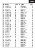
Page 9: ...2 XTAL6MHZ AC AH X700 30001756 XTAL18 432MHZ AE AP COILS REFNo PARTS DESCRIPTION SNCODE EXCODE L101 30018866 LINEFILTERSAFE2X22MH10mmX12 5mm AC AH L102 30001971 FERRITEBEAT 805 BLM21A601S AA AD L103 30001992 FIXEDCOIL10UHQ65K A AA AB L107 NOT2 30007308 CAPCER220PF1KVK PULSE AA AD L203 30001996 FIXEDCOIL22UHQ40K AA AB L206 30001979 FIXEDCOIL1UHQ45M A AA AB L207 30001979 FIXEDCOIL1UHQ45M A AA AB L21...

Page 10: ...AA AA C208 30016126 CAPSMD220NF16VKR 0603 AA AB C209 30016126 CAPSMD220NF16VKR 0603 AA AB REFNo PARTS DESCRIPTION SNCODE EXCODE C210 30016126 CAPSMD220NF16VKR 0603 AA AB C212 30000352 CAPEL100UF16VM AA AB C213 30012609 CAPSMD68NF50VK 0603 AA AB C214 30016126 CAPSMD220NF16VKR 0603 AA AB C215 30016126 CAPSMD220NF16VKR 0603 AA AB C217 30016126 CAPSMD220NF16VKR 0603 AA AB C218 30012610 CAPSMD10NF50VJ ...

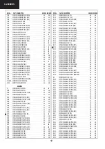
Page 11: ... CAPPP33NF630VK AC AG C618 30000444 CAPCER470PF1KVKB AA AB C619 30000367 CAPEL1UF250VM AA AB REFNo PARTS DESCRIPTION SNCODE EXCODE C621 30023480 CAPMKP10NF2KV 3 5 AB AF C622 30000137 CAPMKP15NF630VJ AC AG C623 30000167 CAPMKPSAFE560NF250VJ AC AK C624 30000172 CAPMKPSAFE680NF250VJ P 15 AC AH C628 30016126 CAPSMD220NF16VKR 0603 AA AB C630 30012603 CAPSMD100NF25VKR 0603 AA AB C631 30000296 CAPCER100N...

Page 12: ...SMF1 4W130KF AA AA R134 30000575 RESSMD1 10W2KJ AA AB REFNo PARTS DESCRIPTION SNCODE EXCODE R137 30000481 RESCF1 4W1MJ AA AB R138 30000660 RESCF1 4W3 3KJ AA AB R139 30000593 RESSMD1 10W2 2KJ 0805 AA AB R140 30001174 RESMO2W0 47RJ AA AB R141 30012641 RESSMD1 16W10KJ 0603 AA AB R142 30012657 RESSMD1 16W1KJ 0603 AA AB R143 30020455 RESSMD1 16W1 5KF 0603 AA AA R144 30000480 RESSMD1 10W100KJ 0805 AA AB...

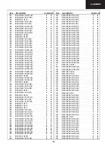
Page 13: ...RESSMD1 16W22KJ 0603 AA AB R4 30000712 RESCF1 4W470RJ AA AB R400 30012669 RESSMD1 16W22KJ 0603 AA AB REFNo PARTS DESCRIPTION SNCODE EXCODE R404 30012692 RESSMD1 16W4 7KJ 0603 AA AB R406 30012650 RESSMD1 16W15KJ 0603 AA AB R409 30012713 RESSMD1 16W75RJ 0603 AA AB R411 30012657 RESSMD1 16W1KJ 0603 AA AB R412 30012657 RESSMD1 16W1KJ 0603 AA AB R413 30012713 RESSMD1 16W75RJ 0603 AA AB R414 30012713 RE...

Page 14: ...A R655 30012674 RESSMD1 16W27KJ 0603 AA AB R656 30012641 RESSMD1 16W10KJ 0603 AA AB R657 30000466 RESCF1 4W1KJ AA AB REFNo PARTS DESCRIPTION SNCODE EXCODE R658 30000466 RESCF1 4W1KJ AA AB R700 30012695 RESSMD1 16W470RJ 0603 AA AB R701 30012695 RESSMD1 16W470RJ 0603 AA AB R702 30012657 RESSMD1 16W1KJ 0603 AA AB R703 30012510 RESSMD1 16W100RJ 0603 AA AB R704 30012510 RESSMD1 16W100RJ 0603 AA AB R705...

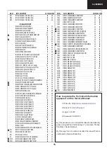
Page 15: ...YSMB2 9 13 AA AB 35000212 SCREWSCZNSYYSMB2 9 13 AA AB 35000214 SCREWSCZNSYYSMB3 5 19 AA AA 35000224 SCREWCSKZNYFMB2 9 9 5 AA AB 35000231 SCREWSKCNIYFMB2 9 6 5 AA AB 35000235 SCREWPCZNAKBR7 32 AA AC 35004572 SCREWPCAgSYFYSB4x20 AA AB 20157329 R C1548SHARP GRAY S AM AY 50043630 WARRANTYCARDSHARP ESP AB AF 50049951 I BSHARPC2890EP AK45 1548 ESP POR AC AK 20157362 LBL BCK CVR SHA EL SHARPC2890E ES 45 ...

Page 16: ...cal photocopying recording or otherwise without prior written permission of the publisher Technical information and Production Vestel Electronik AS Technical information re issued SHARP ELECTRONICA ESPAÑA S A Service Manual Group Engineering Dept Polígono Industrial Can Sant Joan 08190 Sant Cugat del Vallès Barcelona Spain Think Ecology please use RECYCLED PAPER ...

Page 17: ...ations in some countries the set should be re stored to its original condition and only parts identi cal to those specified should be used CONTENTS TABLE OF CONTENTS 3 INTRODUCTION 6 CIRCUIT DESCRIPTIONS 6 INTEGRATED CIRCUIT DESCRIPTIONS 10 SERVICE MODE ADJUSTMENTS 23 BLOCK DIAGRAM 61 CIRCUIT DIAGRAMS 62 HOW TO UPDATE THE TECHNICAL INFORMATION 73 SHARP CORPORATION SE00AK45CHA00 Issued 20th Jan 200...

Page 18: ...c If only part number changes are required just change part number directly the part number in the Parts Listing Section If you need more information please refer to the Technical Report Bulletin SERVICE MANUAL UPDATE LOG SHEET Part No Technical Report No Technical Bulletin No Cause Solution Page No Application Data Serial No ...

Page 19: ...W FILTERS 9 13 IC DESCRIPTIONS 10 13 1 LM317T 10 13 1 1 Description 10 13 1 2 Features 10 13 2 TDA1308T 10 13 2 1 General Description 10 13 2 2 Features 10 13 2 3 Pinning 11 13 3 MSP34X0G MSP3410G 11 13 3 1 Description 11 13 3 2 Features 12 13 3 3 Pin connections 12 13 4 VDP313xY 13 13 4 1 Introduction 13 13 4 2 Features 14 13 4 3 Pin Connections and short descriptions 14 13 5 TEA6415C 15 13 5 1 G...

Page 20: ...ontrol 2 Low Byte 38 Option 13 PLL Tuner Control 2 Mid Byte 39 Option 14 PLL Tuner Control 2 High Byte 39 Option 15 PLL Tuner VHF LOW VHF HIGH Crossover Low Byte 39 Option 16 PLL Tuner VHF LOW VHF HIGH Crossover High Byte 39 Option 17 PLL Tuner VHF HIGH UHF Crossover Low Byte 39 Option 18 PLL Tuner VHF HIGH UHF Crossover High Byte 39 Option 19 PIP PLL Tuner Control 1 Byte 40 Option 20 PIP PLL Tune...

Page 21: ...ICAM Prescaler 45 Option 52 Scart Input Prescaler 45 Option 53 I2S Prescaler 45 Option 54 Scart Output Prescaler 45 Option 55 Speaker Setup 46 Option 56 Audio Options Available Or Not 46 Option 57 Stereo Threshold 46 Option 58 MSP Audio Flags 47 Option 59 NICAM Threshold 47 Option 60 Power Delay Time 47 14 4 OPTION TABLE RECOMMENDED VALUES 50 14 5 SCREEN ADJUSTMENT FBT SCREEN 52 14 6 GEOMETRY ADJU...

Page 22: ...316 1 Member of the UV1300 family small sized UHF VHF tuners 2 Systems CCIR B G H L L I and I OIRT D K 3 Digitally controlled PLL tuning via I2 C bus 4 Off air channels S cable channels and Hyperband 5 World standardized mechanical dimensions and world standard pinning 6 Compact size 7 Complies to CENELEC EN55020 and EN55013 Pinning 1 Gain control voltage AGC 4 0V Max 4 5V 2 Tuning voltage 3 I C b...

Page 23: ...al Audio power amplifier assembled in the Multi watt package specially designed for high quality sound application as Hi Fi music centers and stereo TV sets 7 VERTICAL OUTPUT STAGE WITH STV9379FA The IC STV9379FA is the vertical deflection booster circuit Two supply voltages 14V and 14V are needed to scan the inputs VERT and VERT respectively And a third supply voltage 60V for the flyback limiting...

Page 24: ...able Clock Speed Single external 6MHz crystal all necessary clocks are generated internally CPU clock speed selectable via special function registers Normal Mode 33 33 MHz CPU clock Power Save mode 8 33 MHz 10 3 Microcontroller Features 8bit 8051 instruction set compatible CPU 33 33 MHz internal clock max 0 360 ms min instruction cycle Two 16 bit timers Watchdog timer Capture compare timer for inf...

Page 25: ...of Echo Disturbed Signals 10 7 Ports One 8 bit I O port with open drain output and optional I2 C Bus emulation support Port0 Two 8 bit multifunction I O ports Port1 Port3 One 4 bit port working as digital or analogue inputs for the ADC Port2 One 2 bit I O port with secondary function P4 2 4 3 4 7 One 4 bit I O port with secondary function P4 0 4 1 4 4 Not available in P SDIP 52 11 CLASS AB STEREO ...

Page 26: ...king it essentially blow out proof The LM317 serves a wide variety of applications including local on card regulation This device can also be used to make a programmable output regulator or by connecting a fixed resistor between the adjustment and output the LM317 can be used as a precision current regulator 13 1 2 Features Output Current in Excess of 1 5 A Output Adjustable between 1 2 V and 37 V...

Page 27: ...ormed on a single chip Figure shows a simplified functional block diagram of the MSP 34x0G evaluated internally with subsequent switching between mono stereo bilingual no I2 C interaction is necessary Automatic Sound Selection This new generation of TV sound processing ICs now includes versions for processing the multi channel television sound MTS signal conforming to the standard recommended by t...

Page 28: ... diagram DVSS if not used connect to DVSS AHVSS connect to AHVSS Pin No Pin Name Type Connection if not used Short Description PLCC 68 pin PSDIP 64 pin PSDIP 52 pin PQFP 80 pin PLQFP 64 pin 1 16 14 9 8 ADR_WS OUT LV ADR word strobe 2 NC LV Not connected 3 15 13 8 7 ADR_DA OUT LV ADR Data Output 4 14 12 7 6 I2S_DA_IN1 IN LV I 2 S1 data input 5 13 11 6 5 I2S_DA_OUT OUT LV I 2 S data output 6 12 10 5...

Page 29: ...2 left 51 33 27 33 25 SC2_OUT_R OUT LV SCART output 2 right 52 32 NC LV Not connected 53 32 31 24 NC LV Not connected 54 31 26 30 23 DACM_SUB OUT LV Subwoofer output 55 30 29 22 NC LV Not connected 56 29 25 28 21 DACM_L OUT LV Loudspeaker out left 57 28 24 27 20 DACM_R OUT LV Loudspeaker out right 58 27 23 26 19 VREF2 X Reference ground 2 59 26 22 25 18 DACA_L OUT LV Headphone out left 60 25 21 24...

Page 30: ...4 pin PSDIP package 13 4 3 Pin Connections and short descriptions NC not connected LV if not used leave vacant X obligatory connect as described in circuit diagram IN Input OUT Output SUPPLY Supply Pin Pin no PSDIP 64 pin Pin name Type Connection if not used Short description 1 TEST IN GNDD Test Input 2 RESQ IN X Reset Input 3 SCL IN OUT X I 2 C Bus Clock 4 SDA IN OUT X I 2 C Bus Data 5 GNDD SUPPL...

Page 31: ...Video ADC 58 VSUPAF SUPPLY X Analog Supply Voltage 5 0V Front end 59 VOUT OUT LV Analog Video Output 60 CIN1 IN VRT Analog Chroma 1 Input 61 VIN1 IN VRT Analog Video 1 Input 62 VIN2 IN VRT Analog Video 2 Input 63 VIN3 IN VRT Analog Video 3 Input 64 VIN4 IN VRT Analog Video 4 Input 13 5 TEA6415C 13 5 1 General Description The main function of the IC is to switch 8 video input sources on 6 outputs E...

Page 32: ...n 4 5Vpp 19 Ground 20 Input Max 2Vpp Input Current 1mA Max 3mA 13 6 STV9379FA 13 6 1 Description Designed for monitors and high performance TVs the STV9379FA vertical deflection booster can handle flyback voltage up to 90V Further to this it is possible to have a flyback voltage which is more than the double of the supply Pin 2 This allows to decrease the power consumption or to decrease the flyba...

Page 33: ...table voltages and currents 13 8 2 Features Output Current Up To 1 5 A Output Voltages of 5 5 2 6 8 8 5 9 12 15 18 24V Thermal Over load protection Short Circuit Protection Output Transition SOA Protection 13 9 AT24C08 13 9 1 Description The AT24C01A 02 04 08 16 provides 1024 2048 4096 8192 16384 bits of serial electrically erasable and programmable read only memory EEPROM organized as 128 256 512...

Page 34: ...can also be used for customer defined on screen displays Internal XRAM consists of up to 16 Kbytes Device has an internal ROM of up to 128 KBytes ROMless versions can access up to 1 MByte of external RAM and ROM The SDA 55XX supports a wide range of standards including PAL NTSC and contains a digital slicer for VPS WSS PDC TTX and Closed Caption an accelerating acquisition hardware module a displa...

Page 35: ...Characters Shadowing Contrast Reduction Pixel by Pixel Shiftable Cursor With up to 4 Different Colours Support of Progressive Scan and 100 Hz 3 X 4Bits RGB DACs On Chip Free Programmable Pixel Clock from 10 MHz to 32MHz Pixel Clock Independent from CPU Clock Multinorm H V Display Synchronization in Master or Slave Mode Acquisition Features Multistandard Digital Data Slicer Parallel Multi norm Slic...

Page 36: ...tus and the 120mA level to detect an Over Voltage status called Quick OVP 2 ISENSE The Current Sense pin senses the voltage developed on the series resistor inserted in the source of the power MOSFET When I sense reaches 1V the Driver output pin 5 is disabled This is known as the Over Current Protection function A 200mA current source is flowing out of the pin 3 during the start up phase and durin...

Page 37: ...TR G Leadform 10 16 mm provides creepage distance 8 mm for TCET2100 TCET4100 optional suffix letter G is not marked on the optocoupler Coupling System U 13 13 TDA9885T 13 13 1 General Description The TDA9885 is an alignment free single standard without positive modulation vision and sound IF signal PLL 13 13 2 Features 5 V supply voltage Gain controlled wide band Vision Intermediate Frequency VIF ...

Page 38: ... FM PLL for loop filter DEEM 5 de emphasis output for capacitor AFD 6 AF decoupling input for capacitor DGND 7 digital ground AUD 8 audio output TOP 9 tuner AGC TakeOver Point TOP SDA 10 I2 C bus data input output SCL 11 I2 C bus clock input SIOMA 12 sound intercarrier output and MAD select n c 13 not connected TAGC 14 tuner AGC output REF 15 4 MHz crystal or reference input VAGC 16 VIF AGC for ca...

Page 39: ...rvice menu parameters of AK45 CHASSIS are listed below 14 2 ADJUST MENU Select the parameter by pressing up down buttons Adjust the parameter by pressing Left Right buttons In ADJUST menu changed values are stored automatically White Point Red White Point Green White Point Blue Not used AGC Apply PAL BG signal VHF 3 Channel 12 and 60dBµV signal level Adjust AGC Automatic Gain Control item by press...

Page 40: ...k stop position Angle Change Angle by pressing Left Right buttons till the vertical lines of the crosshatch pattern become completely perpendicular to horizontal lines without any angle of vertical deviation Check and readjust ANGLE item if the adjustment becomes improper after some other geometric adjustments are done Bow Change Bow by pressing Left Right buttons till the vertical lines especiall...

Page 41: ...l amplitude of regular mode REGULAR VERT_SCOR Regular mode Vertical S Correction It s used to adjust the vertical s correction of regular mode REGULAR VERT_SSYM Regular mode Vertical S Symmetry It s used to adjust the vertical s symmetry of regular mode REGULAR TRAPEZE Regular mode Trapeze Change Trapezium by pressing Left Right buttons till vertical lines especially lines at the sides of the pict...

Page 42: ...RAMIC HORZ_AMPL Panoramic mode Horizontal amplitude It s used to adjust the horizontal amplitude of panoramic mode 14 9 ZOOM VERT_POS 14 9 Zoom mode Vertical Position It s used to adjust the vertical position of 14 9 zoom mode 14 9 ZOOM VERT_AMPL 14 9 Zoom mode Vertical Amplitude It s used to adjust the vertical amplitude of 14 9 zoom mode 14 9 ZOOM VERT_SCOR 14 9 Zoom mode Vertical S Correction I...

Page 43: ...OS 16 9 Zoom Subtitle mode Vertical position It s used to adjust the vertical position of 16 9 zoom subtitle mode 16 9 ZOOM SUBTITLE VERT_AMPL 16 9 Zoom Subtitle mode Vertical amplitude It s used to adjust the vertical amplitude of 16 9 zoom subtitle mode 16 9 ZOOM SUBTITLE VERT_SCOR 16 9 Zoom Subtitle mode Vertical S Correction It s used to adjust the vertical s correction of 16 9 zoom subtitle m...

Page 44: ...ED NORMAL The amplitude of R of RGB output can be adjusted with the drive parameter WDR for the colour temperature of normal mode REFERENCE WDR GREEN NORMAL The amplitude of G of RGB output can be adjusted with the drive parameter WDR for the colour temperature of normal mode REFERENCE WDR BLUE NORMAL The amplitude of B of RGB output can be adjusted with the drive parameter WDR for the colour temp...

Page 45: ...WARM The amplitude of B of RGB output can be adjusted with the drive parameter WDR for the colour temp of cool mode STANDARD MODE BRIGHTNESS It s used to adjust the brightness value of standard mode STANDARD MODE COLOUR It s used to adjust the colour value of standard mode STANDARD MODE CONTRAST It s used to adjust the contrast value of standard mode FULL VERT_POS 16 9 MODE It s used to adjust the...

Page 46: ...fixed PERSONAL MODE FACTORY SETTING COLOUR It s fixed PERSONAL MODE FACTORY SETTING CONTRAST It s fixed SCINC FOR PANORAMIC MODE scaler1 coefficient this scaler is compressing the signal SCINC1 FOR PANORAMIC MODE scaler2 coefficient this scaler is expanding the signal VOLUME AFTER APS It s used to adjust the volume level after APS VERTICAL SCROLL It s used to adjust the step width for scroll funct...

Page 47: ...16 9 RGB HORIZONTAL AMPLITUDE It s used to adjust the horizontal amplitude in 16 9 mode for RGB signals 16 9 SUBTITLE RGB HORIZONTAL AMPLITUDE It s used to adjust the horizontal amplitude in 16 9 subtitle mode for RGB signals FULL RGB HORIZONTAL AMPLITUDE It s used to adjust the horizontal amplitude in full mode for RGB signals TELETEXT HORZ_POS It s used to adjust the horizontal position of telet...

Page 48: ...WDG ADJUST 25 WDB ADJUST 26 CR ADJUST 27 CG ADJUST 28 CB ADJUST 29 COR coring level 15 ADJUST 30 NORMAL VERT_POS 127 128 127 ADJUST 31 NORMAL VERT_AMPL 53 81 53 ADJUST 32 NORMAL VERT_SCOR 129 132 133 ADJUST 33 NORMAL VERT_SSYM 136 136 131 ADJUST 34 NORMAL TRAPEZE 129 129 131 ADJUST 35 NORMAL CUSHION 149 155 141 ADJUST 36 NORMAL HOR_COR_SYM 128 123 118 ADJUST 37 NORMAL HOR_CORNER 113 107 137 ADJUST...

Page 49: ...A 0 0 0 ADJUST 88 LSLTB 1 1 0 ADJUST 89 REFERENCE WDR RED NORMAL X X X ADJUST 90 REFERENCE WDR GREEN NORMAL X X X ADJUST 91 REFERENCE WDR BLUE NORMAL X X X ADJUST 92 REFERENCE CUTOFF RED 55 65 55 ADJUST 93 REFERENCE CUTOFF GREEN 69 68 69 ADJUST 94 REFERENCE CUTOFF BLUE 69 77 69 ADJUST 95 IBRM 215 200 215 ADJUST 96 WDRV 68 75 68 ADJUST 97 ACC_SAT COLOR OFFSET 130 154 130 ADJUST 98 G2 CUTOFF REFEREN...

Page 50: ...ST 141 ZOOM 16 9 SUBTITLE RGB HORIZONTAL AMPLITUDE 40 No use 48 ADJUST 142 FULL RGB HORIZONTAL AMPLITUDE 40 18 48 ADJUST 143 TELETEXT HORZ_POS 95 104 98 ADJUST 144 RGB BRIGHTNESS OFFSET 0 80 0 ADJUST 145 RGB CONTRAST OFFSET 0 75 0 ADJUST 146 TELETEXT BRIGHTNESS 100 150 100 ADJUST 147 TELETEXT CONTRAST 120 135 120 ADJUST 148 SVG1 3 3 3 ADJUST 149 SVD1 7 7 7 ADJUST 150 SVLIM 127 127 127 ADJUST 151 S...

Page 51: ... 58 1 2 or 3 crystals Pin 35 No crystal 1 0 Pal BG Pal DK Pal I I Secam BG Secam DK Secam L L Secam K1 Pin 34 No crystal Pin 35 4 43 1 crystal 1 1 Pal BG Pal DK Pal I I Secam BG Secam DK Secam L L Secam K1 Pal M Pal N Ntsc M Pin 34 3 58 1 2 or 3 crystals Pin 35 4 43 1 crystal Option 1 0x01 Video Processor Decoder Mode Register B7 x x B6 x x B5 x x B4 x x B3 x x B2 x x B1 x x B0 x x Option 2 0x18 V...

Page 52: ... for others country option 1 BG 0 DK Option 4 B7 x x B6 x x B5 x x B4 x x B3 x x B2 x x B1 x x B0 x x Option 5 CTI Available Mono AVL B7 x x B6 x x B5 x x B4 x x B3 x x B2 x x B1 x x B0 x x Option 6 B7 TEXT LANGUAGE 3 B6 TEXT LANGUAGE 2 B5 TEXT LANGUAGE 1 B4 x x B3 x x B2 x x B1 x x B0 x x Option 7 OPTIONHOTELACTIVE PLL_VST PIP Zoom Mode PIP Position B7 x x B6 x x B5 F note 1 B4 x x B3 x x B2 PZM ...

Page 53: ...ner Note 4 IfD 1 IF DK 38 0 MHz 0 IF DK 38 9 MHz Note 5 IfM 1 IF M N 45 75 MHz S N American Models Tuner UV1336 Only Pal M N Ntsc M 0 IF M N 38 9 MHz Euro M N Models Standard Tuner Note 6 Aps Only for PLL 0 A P S done 1 A P S set Note 7 Hp Headphone available 0 No headphone 1 Headphone available Note 8 Hue Hue Available 0 No Hue 1 Hue available Option 9 Standard Available B7 NM note 1 B6 PN note 1...

Page 54: ...VHS available Option 11 PLL Tuner Control 1 Byte Pll tuner control 1 byte b7 b6 b5 b4 b3 b2 b1 b0 Philips UV1316T MK3 1 0 0 0 1 1 1 0 Philips UV1316MK2 1 0 0 0 1 1 1 0 Alps TELE9X062A 1 0 0 0 1 1 1 0 Samsung TEXX2949PG28A 1 0 0 0 1 1 1 0 Siel PT060 1 0 0 0 1 1 1 0 Temic 5001PH5 3X0003 1 0 0 0 1 1 1 0 Thomson CTT5020 1 0 0 0 1 1 1 0 Option 12 PLL Tuner Control 2 Low Byte Pll tuner control 2 low byt...

Page 55: ...T060 0 0 0 0 1 0 1 0 Temic 5001PH5 3X0003 0 0 0 0 0 0 0 0 Thomson CTT5020 1 0 1 0 1 0 1 0 AA hex Option 16 PLL Tuner VHF LOW VHF HIGH Crossover High Byte Pll tuner VHF LOW VHF HIGH crossover high byte b7 b6 b5 b4 b3 b2 b1 b0 Philips UV1316T MK3 0 0 0 0 1 1 0 0 Philips UV1316MK2 0 0 0 0 1 1 0 0 0C hex Alps TELE9X062A 0 0 0 0 0 0 0 0 Samsung TEXX2949PG28A 0 0 0 0 1 1 0 1 Siel PT060 0 0 0 0 1 1 0 1 T...

Page 56: ...A 0 0 0 0 0 0 1 0 Siel PT060 1 1 0 1 0 0 0 0 Temic 5001PH5 3X0003 0 0 0 0 0 1 0 0 Thomson CTT5020 0 0 0 0 0 1 1 0 Option 22 PIP PLL Tuner Control 2 High Byte b7 b6 b5 b4 b3 b2 b1 b0 Philips UV1316MK2 0 0 1 1 0 1 0 0 Alps TELE9X062A 0 0 0 0 1 0 0 0 Samsung TEXX2949PG28A 0 0 0 0 1 0 0 0 Siel PT060 0 0 1 1 0 0 0 0 Temic 5001PH5 3X0003 0 0 0 0 0 0 0 1 Thomson CTT5020 1 0 0 0 0 1 0 1 Option 23 PIP PLL ...

Page 57: ...0 0 0 Thomson CTT5020 0 0 0 1 1 0 1 1 1B hex Option 27 Language Available 1 B7 L7 DANISH B6 L6 SWEDISH B5 L5 ITALIAN B4 L4 PORTUGUESE B3 L3 SPANISH B2 L2 FRENCH B1 L1 GERMAN B0 L0 ENGLISH 1 Language available 0 Language not available Option 28 Language Available 2 B7 L15 CROATIC B6 L14 POLISH B5 L13 SLOVAK B4 L12 CZECH B3 L11 HUNGARY B2 L10 GREEK B1 L9 TURKEY B0 L8 NORWEGIAN 1 Language available 0...

Page 58: ... 0 0 I 0 0 1 0 1 F 0 0 1 1 0 RSM 0 0 1 1 1 B 0 1 0 0 0 DK 0 1 0 0 1 S 0 1 0 1 0 N 0 1 0 1 1 FIN 0 1 1 0 0 GB 0 1 1 0 1 IRL 0 1 1 1 0 IS 0 1 1 1 1 NL 1 0 0 0 0 E 1 0 0 0 1 P 1 0 0 1 0 PL 1 0 0 1 1 CZ 1 0 1 0 0 H 1 0 1 0 1 HR 1 0 1 1 0 GR 1 0 1 1 1 TR Option 31 Prescaler MSP FM AVL OFF b7 b6 b5 b4 b3 b2 b1 b0 Prescaler MSP FM AVL OFF 0 0 0 0 1 0 0 0 b7 b6 b5 b4 b3 b2 b1 b0 Prescaler MSP FM AVL OFF 0...

Page 59: ...5 Not used B7 x note 7 B6 x note 6 B5 x note 5 B4 x note 4 B3 AV2S Scart2 SVHS B2 Macro Macrovision B1 DP Dolby Prologic B0 VD Virtual Dolby Option 36 Not used B7 x note 7 B6 TAT 1 Tilt and trapeze enabled B5 SWF 1 Subwoofer enabled B4 VLO 1 Variable line out B3 VBUS 1 Vestelbus enabled B2 x x B1 DVD 1 DVD enabled B0 DVB 1 DVB enabled Option 37 Reserved for USA Option 38 TV Teletext Mode Selection...

Page 60: ...7 b6 b5 b4 b3 b2 b1 b0 EQUALIZER BAND 1 0 0 0 0 0 1 1 0 Option 40 Personal Preference Equalizer Band 2 b7 b6 b5 b4 b3 b2 b1 b0 EQUALIZER BAND 2 0 0 0 0 0 1 1 0 Option 41 Personal Preference Equalizer Band 3 b7 b6 b5 b4 b3 b2 b1 b0 EQUALIZER BAND 3 0 0 0 0 0 1 1 0 Option 42 Personal Preference Equalizer Band 4 b7 b6 b5 b4 b3 b2 b1 b0 EQUALIZER BAND 4 0 0 0 0 0 1 1 0 Option 43 Personal Preference Eq...

Page 61: ...0 3D Panorama 0 0 0 0 1 0 1 1 b7 b6 b5 b4 b3 b2 b1 b0 NICAM Prescaler for Dolby 0 0 0 0 1 1 1 0 Note if virtual Dolby is available this option is not used Option 52 Scart Input Prescaler b7 b6 b5 b4 b3 b2 b1 b0 Scart Input Prescaler for Stereo 0 0 0 0 1 0 0 0 b7 b6 b5 b4 b3 b2 b1 b0 Scart Input Prescaler for Dolby 0 0 0 0 1 1 1 1 b7 b6 b5 b4 b3 b2 b1 b0 Prescaler MSP Scart AVL OFF 0 0 0 1 1 0 0 1 ...

Page 62: ... 1 VRS available Note 4 CRM CARRIER MUTE OFF ON 0 Sound carrier mute is ON in the Stereo Sound IC 1 Sound carrier mute is OFF in the Stereo Sound IC i e option available Note 2 LBE LBE Dynamic Bass 0 LBE not available 1 LBE available Note 1 Spa Spatial Effect available 0 Spatial Effect not available 1 Spatial Effect available Note 0 Avl Automatic volume level available on the Menu 0 Automatic volu...

Page 63: ...L4L3L2L1L0 Delay 0 00000000 4 Sec 32 00100000 12 Sec 1 00000001 4 25 Sec 33 00100001 12 25 Sec 2 00000010 4 5 Sec 34 00100010 12 5 Sec 3 00000011 4 75 Sec 35 00100011 12 75 Sec 4 00000100 5 Sec 36 00100100 13 Sec 5 00000101 5 25 Sec 37 00100101 13 25 Sec 6 00000110 5 5 Sec 38 00100110 13 5 Sec 7 00000111 5 75 Sec 39 00100111 13 75 Sec 8 00001000 6 Sec 40 00101000 14 Sec 9 00001001 6 25 Sec 41 0010...

Page 64: ...c 55 00110111 17 75 Sec 24 00011000 10 Sec 56 00111000 18 Sec 25 00011001 10 25 Sec 57 00111001 18 25 Sec 26 00011010 10 5 Sec 58 00111010 18 5 Sec 27 00011011 10 75 Sec 59 00111011 18 75 Sec 28 00011100 12 Sec 60 00111100 19 Sec 29 00011101 12 25 Sec 61 00111101 19 25 Sec 30 00011110 12 5 Sec 62 00111110 19 5 Sec 31 00011111 12 75 Sec 63 00111111 19 75 Sec ...

Page 65: ...0101011 12 00001100 44 00101100 13 00001101 45 00101101 14 00001110 46 00101110 15 00001111 47 00101111 16 00010000 48 00110000 17 00010001 49 00110001 18 00010010 50 00110010 19 00010011 51 00110011 20 00010100 52 00110100 21 00010101 53 00110101 22 00010110 54 00110110 23 00010111 55 00110111 24 00011000 56 00111000 25 00011001 57 00111001 26 00011010 58 00111010 27 00011011 59 00111011 28 00011...

Page 66: ...XX XXXXXXXX 023 XX XXXXXXXX XX XXXXXXXX XX XXXXXXXX 024 XX XXXXXXXX XX XXXXXXXX XX XXXXXXXX 025 XX XXXXXXXX XX XXXXXXXX XX XXXXXXXX 026 XX XXXXXXXX XX XXXXXXXX XX XXXXXXXX 027 FF 11111111 FF 11111111 FF 11111111 028 FF 11111111 FF 11111111 FF 11111111 029 FF 11111111 EF 11101111 EF 11101111 030 XX XXXXXXX XX XXXXXXX XX XXXXXXX 031 0F 00001111 0F 00001111 0F 00001111 032 23 00100011 23 00100011 23 ...

Page 67: ... 01110101 055 00 00000000 00 00000000 00 00000000 056 DE 11011110 DE 11011110 DE 11011110 057 19 00011001 19 00011001 19 00011001 058 00 00000000 00 00000000 00 00000000 059 64 01100100 64 01100100 64 01100100 060 10 00010000 10 00010000 10 00010000 ...

Page 68: ...EEN ADJUSTMENT FBT SCREEN From the option list change option 2 bit 6 from 0 to 1 for disabling vertical scan Adjust horizontal line via screen adjust pot as thin as possible Then press 0 to leave service menu SCREEN ADJUST POT ...

Page 69: ...53 AK 45 CHASSIS 14 6 GEOMETRY ADJUSTMENT 4 3 FORMATS 4 3 MODE 16 9 MODE ...

Page 70: ...54 AK 45 CHASSIS 16 9 FORMATS AUTO MODE ...

Page 71: ...55 AK 45 CHASSIS REGULAR MODE ...

Page 72: ...56 AK 45 CHASSIS ZOOM 14 9 MODE ...

Page 73: ...57 AK 45 CHASSIS ZOOM 16 9 MODE ...

Page 74: ...58 AK 45 CHASSIS SUBTITLE ZOOM MODE ...

Page 75: ...59 AK 45 CHASSIS FULL MODE ...

Page 76: ...60 AK 45 CHASSIS PANORAMIC MODE ...

Page 77: ...DVD DVB PIP R G B FB CVBS R G B FB SCL SDA SYNC SC3 R G B Horizontal Vertical Stage STV9379FA Yoke CRT RGB AMPLIFIER TDA 6107 PHILIPS R G B QSS MSP34XXG SCL SDA SC1 SC2 FRONT SC3 TDA1308 L R Headphone TDA7269A AUDIO AMPLIFIER L R 8 ohm 12W 8 ohm 12W SDA5555 MicroController 24CO8 E2PROM SDA SCL TV_LINK CVBS_TEXT OSD_R OSD_G OSD_B OSD_FBL DVD DVB BAV SC1_V_OUT SC3_V_OUT 15 BLOCK DIAGRAM General Bloc...

Page 78: ...62 AK 45 CHASSIS 16 CIRCUIT DIAGRAMS 16 1 Schematic Diagram of Video IF Circuit 1 I H G F E D C B A 2 3 4 5 6 7 Page 63 ...

Page 79: ...63 AK 45 CHASSIS 8 9 10 11 12 13 14 I H G F E D C B A Page 62 16 1 Schematic Diagram of Video IF Circuit ...

Page 80: ...64 AK 45 CHASSIS 16 2 Schematic Diagram of µ Controller Circuit 1 I H G F E D C B A 2 3 4 5 6 7 ...

Page 81: ...65 AK 45 CHASSIS 8 9 10 11 12 13 14 I H G F E D C B A 11SW01 3 16 3 Schematic Diagram of Deflection Circuit 16 4 Schematic Diagram of Power Switch Circuit ...

Page 82: ...66 AK 45 CHASSIS 1 I H G F E D C B A 2 3 4 5 6 7 Page 67 16 5 Schematic Diagram of SMPS Circuit ...

Page 83: ...67 AK 45 CHASSIS 8 9 10 11 12 13 14 I H G F E D C B A Page 66 16 5 Schematic Diagram of SMPS Circuit ...

Page 84: ...68 AK 45 CHASSIS 1 I H G F E D C B A 2 3 4 5 6 7 Page 69 16 6 Schematic Diagram of Sound Circuit ...

Page 85: ...69 AK 45 CHASSIS 8 9 10 11 12 13 14 I H G F E D C B A Page 68 16 6 Schematic Diagram of Sound Circuit ...

Page 86: ...70 AK 45 CHASSIS 1 I H G F E D C B A 2 3 4 5 6 7 16 7 Schematic Diagram of CRT Socket Circuit ...

Page 87: ...71 AK 45 CHASSIS 8 9 10 11 12 13 14 I H G F E D C B A 16 8 Schematic Diagrams of Control Panel Unit ...

Page 88: ...72 AK 45 CHASSIS 1 I H G F E D C B A 2 3 4 5 6 7 16 9 Schematic Diagram of Remote Control Circuit ...

Page 89: ...be found a Label in every chassis with additional information i e the used EEPROM See below On the next page are given details about the Code Bar Label 17 2 NVM EEPROM recorder There is available the NVM EEPROM recorder as spare part Part Reference V20096887 Description MD ASY PONYPROG Dom Price Code AT Exp Price Code BE This EEPROM recorder uses the free software Pony available at http www lancos...

Page 90: ...roduct code It is the code that indicates Vestel internal identification number of the complete TV set Year Production year in two digits e g 02 for 2002 Month Production month in two digits e g 04 for April Batch number It is a Vestel number that is assigned by the Planning Dept according to the customer orders For internal use by Vestel Consecutive Number The number that indicates the sequence o...

Page 91: ...75 AK 45 CHASSIS Notes ...

Page 92: ...nical photocopying recording or otherwise without prior written permission of the publisher Technical information and Production Vestel Electronik AS Technical information re issued SHARP ELECTRONICA ESPAÑA S A Service Manual Group Engineering Dept Polígono Industrial Can Sant Joan 08190 Sant Cugat del Vallès Barcelona Spain Think Ecology please use RECYCLED PAPER ...

Reviews: