background image

CODE: 00ZDMFX1//A1E

DIGITAL COPIER
FAX EXPANSION KIT

(For USA/Canada)

DM-FX1

EXPANSION 2MB: AR-MM5

MEMORY

4MB: AR-MM6

MODEL

8MB: AR-MM7

[ 1 ] OUTLINE  .  .  .  .  .  .  .  .  .  .  .  .  .  .  .  .  .  .  .  .  .  .  .  .  .  .  .  1  -  1

[ 2 ] SPECIFICATIONS  .  .  .  .  .  .  .  .  .  .  .  .  .  .  .  .  .  .  .  .  .  .    2  -  1

[ 3 ] INSTALLING  PROCEDURE  .  .  .  .  .  .  .  .  .  .  .  .  .  .  .  .  .  3  -  1

[ 4 ] ADJUSTMENTS .  .  .  .  .  .  .  .  .  .  .  .  .  .  .  .  .  .  .  .  .  .  .  .  4  -  1

[ 5 ] SIMULATIONS  .  .  .  .  .  .  .  .  .  .  .  .  .  .  .  .  .  .  .  .  .  .  .  .  5  -  1

[ 6 ] SOFTWARE  SWITCH  DESCRIPTIONS  .  .  .  .  .  .  .  .  .  .  .  6  -  1

[ 7 ] USER  PROGRAMS .  .  .  .  .  .  .  .  .  .  .  .  .  .  .  .  .  .  .  .  .  .  7  -  1

[ 8 ] PRINTING  .  .  .  .  .  .  .  .  .  .  .  .  .  .  .  .  .  .  .  .  .  .  .  .  .  .  .  8  -  1

[ 9 ] FIRMWARE  VERSION  UP  PROCEDURE .  .  .  .  .  .  .  .  .  .  9  -  1

[10] TROUBLE  CODE  LIST  .  .  .  .  .  .  .  .  .  .  .  .  .  .  .  .  .  .  .  10  -  1

CONTENTS

Parts marked with “  ” are important for maintaining the safety of the set. Be sure to replace these parts with specified
ones for maintaining the safety and performance of the set.

SHARP CORPORATION

This document has been published to be used
for after sales service only.
The contents are subject to change without notice.

DM-FX1

Summary of Contents for DM-FX1

Page 1: ... DESCRIPTIONS 6 1 7 USER PROGRAMS 7 1 8 PRINTING 8 1 9 FIRMWARE VERSION UP PROCEDURE 9 1 10 TROUBLE CODE LIST 10 1 CONTENTS Parts marked with are important for maintaining the safety of the set Be sure to replace these parts with specified ones for maintaining the safety and performance of the set SHARP CORPORATION This document has been published to be used for after sales service only The conten...

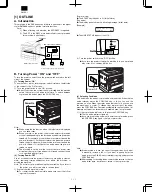
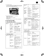
Page 2: ...ng the machine Note Do not turn of power while using the fax machine If you turn off the power you will not be able to receive faxes 1 Confirm that the machine is idle To confirm that the machine is idle make sure one of the follow ing conditions exists Copier mode The START key indicator is lit Initial state Fax mode The display panel shows the following message initial state Example The LINE STA...

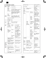
Page 3: ... 17 to 8 5 5 5 OC YES A3 to A5 11 17 to 8 5 5 5 Transmission mode SPF OC transmission changeover NO changeover cannot be made at any time during document scanning Document loading capacity scanning cycle SPF RSPF Automatic feed compatibility YES Document loading capacity 30 sheets Document scanning cycle 18 sheets min Standard mode A4R memory transmission No rotate Document scanning speed 3 3 sec ...

Page 4: ...ission reservations that can be made 50 transmissions Processing when memory is full Transmission cancel or transmission of scanned data only Setting change after trans mission setting NO Direct transmission YES SPF 30 sheet OC 1 sheet Default setting Setting made in user program Line sound moni toring function Dialing confirmation monitoring YES Volume adjustment made muting enable in soft SW Bro...

Page 5: ...ed tray setting in user program Enlargement NO Memory receiving function Substitute receiving into memory Only when data cannot be output Forced memory receiving NO Received data override output NO Transfer Transfer at occurrence of trouble YES by user program setting Transfer method By the special transmission key in case of a trouble Number specified receiving Receiving of only specified number ...

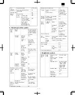
Page 6: ...ethod By pressing the program key Setting change after calling NO Sender registration Sender s name 40 half size letters registered in user program Sender s number 20 digits registered in user program Polling Memory Polling security Polling enable number Polling source number registration 10 numbers 20 digits System number System number registration Up to 1 number registered in user program ID num...

Page 7: ...ication table Common to transmission record table Confidential receiving confirmation table YES Communica tion result table function Communication result table transmission YES any of always output only when transmission could not be made not output is set in user program Broadcast transmission report YES any of always output only destination to which transmission could not be made not output is s...

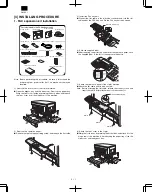
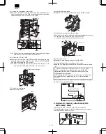
Page 8: ...l stick the supplied label to the left of the exposure indicators 5 Attach the operation panel of the copier machine Attach the flat cable and fix with a screw Note Before attaching the flat cable release the connector lock and insert the cable After attachment lock the connector 6 Attach the front cover to the copier Warp the front cover by pressing the both sides and attach it to the hinge arm o...

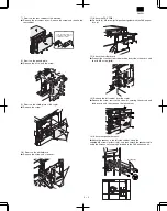
Page 9: ...ch the motherboard Connect the connector from the machine insert the connectors and fix with M3 screw gold 13 Remove the left cabinet from the copier Remove the screw remove the screw for securing the second and third mirrors and then remove the left cabinet 14 Attach the speaker harness Attach the speaker to the left side cabinet using the supplied M3 screws gold color 8 and then secure the speak...

Page 10: ...th the screw and attach the document cover 20 Time setup check Change the time setup referring to the SIM 26 22 21 Stick the label to the rear cabinet of the copier Stick the FCC Registration Label to the position shown in the illustra tion In order to manifest the compliance with FCC Part 68 and IC CS 03 it is required to provide the machine with the FCC Registration Number USA Ringer Equivalence...

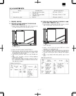
Page 11: ...Adjustment specifications Den sity mode Resolution mode SIM CCITT 3 chart output result Set value Set range Auto Standard FAX mode 46 12 3 is slightly copied The greater the set value is the greater the density is and vice versa 1 99 B FAX mode density adjustment Individual mode FAX mode SIM 46 14 16 1 Set the test chart TRAP23109SCZZ CCITT 3 chart on the OC table as shown below and close the OC c...

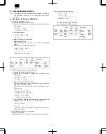
Page 12: ...TMF mode according to the instructions on the LCD display SELECT SIGNAL 1 PULSE 2 DTMF 3 Select the signal transmission level The signal transmission level is classified into two groups the high group and the low group Transmission can be made with either of default and the soft SW set value SELECT HIGH LEVEL 1 DEFAULT 2 SOFT SW SELECT LOW LEVEL 1 DEFAULT 2 SOFT SW 4 The transmission level can be ...

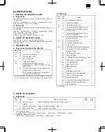
Page 13: ...de Content 22 11 Fax related counter display 14 Fax ROM ver Display 24 14 FAX related counter clear 46 12 FAX mode density adjustment AUTO 14 FAX mode density adjustment for each resolution Fine 15 FAX mode density adjustment for each resolution Super Fine 16 FAX mode density adjustment for each resolution Ultra Fine 64 02 User switch front print 03 Soft switch setting table print 04 Dump list pri...

Page 14: ...alling an option When A is displayed on the display Shifter Paper empty LED Job separator JAM LED SPF SPF select LED RSPF SPF JAM LED Dehumidifier heater Main body JAM LED Duplex mode Main cassette select LED Simplex mode Multi manual feed select LED When b is displayed on the display Cassette 2 stage No 2 cassette select LED Cassette 3 stage No 3 cassette select LED Cassette 4 stage No 4 cassette...

Page 15: ...warming up shading is performed and the currently set density level Ultra fine mode is displayed For the adjustment procedures refer to the previous descriptions 64 02 User switch table print Used to print the currently set user switch table 03 Soft switch setup table print Used to print the currently set soft switch FAX send counter communication time option status ROM version 04 Dump list print ...

Page 16: ...ta are also outputted Image data received in a confidential communication remote send image data read in the memory Note Image data are cleared after being outputted 08 Voice message send Not used Used to send the voice reply message 10 Image memory clear Used to clear all data stored in the image memory The following data are also cleared Image data received in confidential communication The mana...

Page 17: ...e Transmission From sending of the flag signal before sending of the image data to sending of RCP frame Reception From reception of the flag signal before reception of the image data to reception of RCP frame The communication test is performed in the standard display After completion of communication the time measured in this mode is checked The setup items in transmission are as follows Communic...

Page 18: ...ne is connected do not select Manual However setup is possible and reception can be made by on hook Auto reception 0 Manual can be set only when an external telephone is connected 5 Send request protection Used to set enable disable of the confidential function inhibition against erroneous transmission during send request communication remote transmission The confidential function is performed wit...

Page 19: ... in memory transmission The set range is 0 to 15 min in the increment of 1 min by binary input When set to 0 recall is made immediately after disconnection However the time interval set by SW21 Interval between the end of a communication and the next call is taken 1 min 0 113 2 0 3 0 4 1 5 Recall interval in case of busy state Used to set recall interval after disconnection of communication due to...

Page 20: ...s is because ANSam signal send is indispensable in V 34 mode This machine uses the ANSam signal also as the CED signal YES 1 Effective only when V 34 mode function are disable 3 CSI send Used to set whether CSI signal send is perform or not The CSI signal includes the transmitter No YES 1 4 DIS reception check in G3 send Used to set whether DIS reception is checked or not in G3 mode Once when rece...

Page 21: ... the start speed of reception procedure when receiving from an other party other than V 34 Reception procedure is made in the set speed No fixing 0 Setup in a communication other than V 34 8 0 SW8 1 Memory transmission Dire ct transmission default setup Used to set whether the transmission mode is memory transmission or direct transmission after pressing C A key or in auto clear operation Memory t...

Page 22: ...ication time in the latest phase C Unit msec YES 1 2 Transmitter TEL number registration Used to set Enable Disable of registered transmitter telephone number change Enable 0 3 Reserved 0 4 Reserved 0 5 Reserved 0 6 Reserved 0 7 Reserved 1 8 Reserved 0 SW11 1 Reserved 1 2 Reserved 0 3 Reserved 0 4 Reserved 0 5 Reserved 0 6 Reserved 0 7 Reserved 0 8 Reserved 0 SW12 1 Reserved 0 2 Reserved 0 3 Reser...

Page 23: ... mode When set to 2400 bps SW58 No 1 6 must be changed to 2400 only 33600 bps 1 When set to 2400 bps SW58 No 1 6 must be set accordingly 2 1 3 1 4 0 5 V 34 mode reception speed Used to set the reception speed when starting reception in V 34 mode When set to 2400 bps SW58 No 1 6 must be changed to 2400 only 33600 bps 1 When set to 2400 bps SW58 No 1 6 must be set accordingly 6 1 7 1 8 0 SW13 Bit No...

Page 24: ... 3 Reserved 0 4 Reserved 0 5 Reserved 0 6 Rotation transmission select 8 5 11 8 5 11 R Used to set whether 8 5 11 document is sent as 11 17 width 8 5 11 or it is sent as 8 5 11 R by rotating read images YES 1 125 7 Reserved 0 8 Reserved 0 SW17 1 Reserved 0 2 Output conditions setup Used to set the size of paper to output when a document is received A Optimum size output Received size B Larger than...

Page 25: ...achine is of inch spec and sends documents of 11 width there is no problem If the other party s machine is of AB spec and sends document of A3 width data are cut 303 255 215 mm 0 2 Refer to the following descriptions 6 Output method in A3 width reception Used to set the output method when A3 width data are sent from the other party s machine 11 width print 0 126 7 Reserved 0 8 Reserved 0 SW19 1 Pr...

Page 26: ... Until NSF signal send receive monitoring is made until the NSF signal is sent or received When set to All monitoring is made for all until the line is disconnected OFF 0 When set to 11 set to 00 2 0 3 Line monitor display Used to set whether the communication speed and the reception level are displayed on the LCD or not NO 0 4 Operation panel key sound Used to set whether the key click sound of F...

Page 27: ...nt output setup Used to set whether all received documents are outputted at a time after completion of reception or each document is outputted every time when it is received Each document is outputted every time when it is received 0 7 Reserved 0 8 Auto reduction print Used to set whether auto reduction print is made or not when the received document size is greater than the fixed size and smaller...

Page 28: ...ration panel sound volume send end sound volume receive end sound volume read end sound volume Small 0 104 4 1 5 Reserved 0 6 Reserved 0 7 Reserved 0 8 Reserved 0 SW27 1 Reserved 0 2 Recording paper tray select Used to select the tray for output of the received documents Tray 1 Tray 4 can be set to ON OFF individually When set to OFF the tray does not output received documents ON 1 134 When set to...

Page 29: ...nagement Used to set Enable Disable of FAX using dept management by the use of the dept management function Disable 0 101 If the dept code is not set Enable cannot be selected 5 Default date transmitter print Used to set whether the transmitter information registered in the transmitter registration and data and time are printed in the upper fringe of the transmitted documents or not ON 1 6 Reserve...

Page 30: ...er the communication report table is outputted or not when a reception excluding confidential reception is made Print inhibited 0 137 When set to 11 set to 00 Print inhibited 6 0 7 Reserved 0 8 Reserved 0 SW32 1 Distinctive ring Used to set the ring pattern of FAX reception 0 110 When a bit other than the specified on the left is set the initial value 0000 OFF is set 2 0 3 0 4 0 5 Reserved 0 6 Ind...

Page 31: ...0 SW35 1 Cover paper function default setup Used to set the cover paper setup to the default When auto clear is made after pressing the C A key the machine returns to this mode NO 0 2 Reserved 0 3 CI signal extinction max OFF time If the next CI signal pulse is not detected within the max wait time until the next CI signal pulse is detected after detection of a CI signal pulse number of times the ...

Page 32: ...et the call time when call does not reach the other party in auto send mode The set range is 30 60 sec in the increment of 5 sec by binary input of 5 sec N 30 sec N can be set in the range of 0 7 When set to 7 65 sec it is the same as setup of 45 sec 45 sec 0 116 When set to 111 set to 011 2 1 3 1 4 Reserved 0 5 Reserved 0 6 Reserved 0 7 Reserved 0 8 Reserved 0 SW40 1 Number of recall times in cas...

Page 33: ...e initial value of 1001 is set When set to 10 or more times set to 9 6 0 7 0 8 1 SW43 1 DTMF signal send time Used to set the DTMF signal send time when sending it The set range is 60 310 ms by binary input of 10 ms N N can be set in the range of 6 31 110 ms 0 When set to under 00101 set to 01011 2 1 3 0 4 1 5 1 6 Reserved 0 7 Reserved 0 8 Reserved 0 SW44 1 Tone Pulse default setup Used to set the...

Page 34: ...ar SW 45 No 2 No 3 10 NO 0 4 Reserved 0 5 Daylight saving time Used to set Enable Disable of Daylight saving time Disable 0 144 6 Reserved 0 7 Reserved 0 8 Reserved 0 SW47 1 Time designation 1 hour print on the activity report Used to set time designation 1 hour to be printed on the activity report 00 0 139 When set to 24 31 it is set to 00 2 0 3 0 4 0 5 0 6 Reserved 0 7 Reserved 0 8 Reserved 0 SW...

Page 35: ...000 ms 0 7 Reserved 0 8 Reserved 0 SW52 1 Reserved 0 2 Reserved 0 3 Reserved 0 4 Reserved 0 5 RTN reception error process Used to set whether RTN reception is treated as a communication error or not Treated as an error 0 6 V 34 mode function in manual communication Used to set ON OFF of V 34 mode function on the other party side in manual communication If SW52 7 is set to 0 OFF though SW52 6 is se...

Page 36: ...me Used to set the min OFF time for judgement of CI pulse 16Hz call signal When OFF time continues for more than the set time it is judged as 1 pulse of CI Set value 10 ms 1200 ms 1 2 1 3 1 4 1 5 0 6 0 7 0 8 Reserved 0 SW56 1 Reserved 0 2 Reserved 0 3 Reserved 0 4 Reserved 0 5 Reserved 0 6 Reserved 0 7 Reserved 0 8 Reserved 0 SW57 1 Reserved 0 2 Reserved 1 3 EQM dispersion deterrence Used to set w...

Page 37: ... Mask Used to set whether 2800 is supported as the symbol rate in V 34 communication or not Supported 1 5 Reserved 0 6 V 34 2400 Baud Rate Mask Used to set whether 2400 is supported as the symbol rate in V 34 communication or not Supported 1 7 Reserved 1 8 Reserved 1 SW59 1 Reserved 1 2 Reserved 1 3 Reserved 0 4 Reserved 0 5 Reserved 0 6 Reserved 0 7 Reserved 0 8 Reserved 0 SW60 1 Reserved 1 2 Res...

Page 38: ... Reserved 0 3 Reserved 0 4 Reserved 1 5 Reserved 0 6 Reserved 0 7 Reserved 1 8 Reserved 1 SW64 1 Reserved 0 2 Reserved 1 3 Reserved 0 4 Reserved 0 5 Reserved 0 6 Reserved 1 7 Reserved 1 8 Reserved 0 SW65 1 Reserved 0 2 Reserved 1 3 Reserved 0 4 Reserved 0 5 Reserved 0 6 Reserved 0 7 Reserved 1 8 Reserved 0 SW66 1 Reserved 0 2 Reserved 0 3 Reserved 1 4 Reserved 0 5 Reserved 0 6 Reserved 0 7 Reserve...

Page 39: ...ed 0 3 Reserved 0 4 Reserved 0 5 T1 timer setup Used to set T1 timer 40 sec 0 6 0 7 1 8 0 SW69 1 Reserved 0 2 Reserved 0 3 Reserved 0 4 Reserved 0 5 Reserved 0 6 Reserved 0 7 Reserved 0 8 Reserved 0 SW70 1 Reserved 1 2 Reserved 0 3 Reserved 0 4 Reserved 0 5 Reserved 0 6 Reserved 1 7 Reserved 0 8 Reserved 0 SW71 1 Reserved 0 2 Reserved 0 3 Reserved 0 4 Reserved 0 5 Reserved 1 6 Reserved 1 7 Reserve...

Page 40: ...ransmission end sound Buzzer length setup Used to set the transmission end sound outputted from the speaker when ending a transmission Though set to Silent in case of a communication error the buzzer sounds for 3 sec 3 sec 0 0 When set to 11 it is set to 00 2 0 3 Reception end sound Buzzer length setup Used to set the reception end sound outputted from the speaker when ending a transmission Though...

Page 41: ...eserved 0 7 Reserved 0 8 Reserved 0 SW77 1 Reserved 0 2 Reserved 0 3 Reserved 0 4 Reserved 0 5 Reserved 0 6 Reserved 0 7 Reserved 0 8 Reserved 0 SW78 1 Reserved 0 2 Reserved 0 3 Reserved 0 4 Reserved 0 5 Reserved 0 6 Reserved 0 7 Reserved 0 8 Reserved 0 SW79 1 Reserved 0 2 Reserved 0 3 Reserved 0 4 Reserved 0 5 Reserved 0 6 Reserved 0 7 Reserved 0 8 Reserved 0 DM FX1 6 24 ...

Page 42: ... before an automatic transmission stops when there is no answer from the recipient s fax 117 OF RINGS AUTO RX SETTING SW29 5 8 Set to change the number of rings for automatic reception 118 POLLING SECURITY SETTING SW1 5 Sets polling security so that only designated people can poll your fax machine 119 PASSCODE SETTING No soft SW Use to create passcodes that contain the numbers of the fax machines ...

Page 43: ... made in user programs 2 How to use user programs You cannot change user programs during a fax transmission or recep tion 1 Select fax mode If the copier mode indicator is lit press the COPY FAX key 2 Press and hold the light key for more than 5 seconds The following message is displayed 3 Enter the desired user program number 3 digit using the numeric keys then press the START key The user progra...

Page 44: ...ART key Example The lower line of the display shows the type of list or report you are printing The fax machine compiles the list you requested and automatically prints it Printing Options 1 Timer List 6 Passcode List 2 Activity List 7 Relay Group List 3 Telephone Number List 8 Confidential Reception List 4 Group List 9 Department Usage List 5 Program List Only when auditing is set Canceling When ...

Page 45: ... sending a confidential fax 1 The other fax machine does not have the confidential fax receiving function or is not a SHARP product 2 The other fax machine has only one confidential box and the passcode has not been entered in it NO REL FUNC When making a relay request 1 The other fax machine does not have the relay fax function 2 The other fax is not a SHARP product CONF TX CNCL 1 You made a mist...

Page 46: ...Q FAIL When receiving a relay request the fax number of the requesting fax machine has not been entered into your Relay Passcode List A REL REQUEST WAS NOT SUCCESSFUL When requesting fax machine created a relay group with an automatic dialing number that does not exist on the relay station fax machine ERRORxx xxxx Because of poor line conditions a telephone line error prevented the reception COM E...

Page 47: ...XXX XXXX PROGRAM XXXXXXXXXXXX FAX XXXXXXXXXXXXXX RAPID XX XX XX XX GROUP XXXXXXXXX SPEED XXXXXXXXXX MSG BOX PROGRAM NAME RECEIVER CONT RES CVR SEP 10 1999 FRI 06 30 PM GROUP LIST P 01 RAPID XX SPEED XXX FAX XXXXXXXXXXXXXXXXXXXXX FAX XXXXXXX XXXXXXXX XXXXXX SPEED XXX XXX RECEIVER GROUP NAME GXX GXX GXX XXXX XXXX XXXX SEP 10 1999 FRI 06 30 PM TELEPHONE NUMBER LIST P 01 RECEIVER S FAX INTL TX SET RAP...

Page 48: ...CODE RELAY ID SENDER S NAME SENDER S FW STA NAME FW RECIEVER XXXXXXXXXXXXXXXXXX XXXXXXXXXXXXXXXX XXXXXXXXXXXXXXXXXXXX XXXXXXXXXXXXXXXX XXXX 01 02 03 04 05 06 07 08 09 10 01 02 03 04 05 06 07 08 09 10 01 02 03 04 05 06 07 08 09 10 XXXX XXXX XXXXXXXXXX XXXXXXXXXX XXXXXXXXXXXX XXXX SEP 10 1999 FRI 06 30 PM RELAY GROUP LIST P 01 XX REL STA FAX XXXXXXX RAPID XX XX XX XX XX SPEED XX XX XX XX XX GROUP XX...

Page 49: ...failed broadcast operations Do not print a transaction report 3 When Printing Reports for Receptions Print a transaction report after every reception operation Print a transaction report only after errors Do not print a transaction report 4 When Printing Reports for Confidential Receptions Print a transaction report after every confidential reception operation Do not print a transaction report 5 C...

Page 50: ...ram operation 1 Starting the program Double click MFP exe in the installed folder or execute the pro gram from the start menu This program cannot be multi started When it is tried to be multi started an error message will be shown 2 Descriptions of the main menu When MFP exe is executed the following main menu is displayed The main menu shows the following information Slot status Slot The selected...

Page 51: ...r to the descriptions below To specify the format type manually specify the items following Card C _SetCardType T in the menu The current operation mode of the application is displayed in the CardType section The File F menu which can be operated differs depending on the operaton mode of the application The CardType is changed when the ProgramArea is erased or data are written into it 6 Erase eras...

Page 52: ...erase Erase check Data read and write verify check of written data To interrupt the process press the ESC key After completion of data write initialize the main menu again The data are read from the card 7 After completion of writing turn off the power of the notebook PC and remove the card adapter 8 Set the write protect switch to ON 4 Writing to main PWB flash ROM 1 Necessary tools Small flash c...

Page 53: ... error Cause Bad connection of FAX control PWB connector Harness trouble between Fax control PWB and MCU PWB Motherboard connector pin breakage FAX control PWB ROM trouble data error Check and remedy Check connection and harness between the FAX control PWB and the MCU PWB Check grounding of the machine Check the FAX control PWB ROM Main code Sub code Details of trouble F6 82 Content FAX control PW...

Page 54: ...reception data of one page exceeds the range during reception 43 Communication OK Communication enable before transmission 44 Document error A document jam during direct transmission Error code Communication result Communication report result column Communication interruption content 45 Image quality error 46 No response from the other party The FAX signal from the other party cannot detect within...

Page 55: ...l channel 91 Error in the first CC train 92 Timeout standby for PPh 93 Tone A B detected in CC retrain 94 Timeout standby for ALT 95 Ach found 96 FED OFF with CC data 97 Timeout standby for turning off CC A1 A trouble which cannot be solved in phase 2 Retrain is forcibly made B1 Trouble in S sequence of HDX resync B1 FED OFF in S sequence of HDX resync B2 Unexpected completion of S sequence in HDX...

Page 56: ...larity reversion detection Reception 12 Invalid command reception Reception 13 Time over 1min timer 6sec timer Reception 14 PUT error Reception 15 Time out occurrence during shift from Primary to Control in V 34 mode Reception 20 Polarity reversion detection Transmission 21 Invalid command reception Transmission 22 Fall back retry number over Transmission 23 Resend over of retry number Transmissio...

Page 57: ...ti French ATTENTION Il y a danger d explosion s il y a remplacement incorrect de la batterie Remplacer uniquement avec une batterie du même type ou d un type équivalent recommandé par le constructeur Mettre au rebut les batteries usagées conformément aux instructions du fabricant Swedish VARNING Explosionsfara vid felaktigt batteribyte Använd samma batterityp eller en ekvivalent typ som rekommende...

Page 58: ...y any means electronic mechanical photocopying recording or otherwise without prior written permission of the publisher Trademark acknowledgments All other trademarks and copyrights are the property of their respective owners SHARP CORPORATION Digital Document Systems Group Quality Reliability Control Center Yamatokoriyama Nara 639 1186 Japan 1999 July Printed in Japan N DM FX1 ...

Reviews: