background image


   K)


 R)


 P)


   L)

PHOTO: 

in the interests of user-safety the set should be restored to its

original condition and only parts identical to those specified be

used.


SPECIFICATIONS . . . . . . . . .

S T R I N G I N G   O F   D I A L   C O R D   .   .   .   .

NAMES OF PARTS . . . . . . . , . . .

DISASSEMBLY . . . . . . . . . . . . . .

BLOCK DIAGRAM . . . . . . . . .
CIRCUIT ADJUSTMENT . . . . . . . .

M E C H A N I C A L   A D J U S T M E N T   .   .   .   .

EXPLODED VIEW . . . . . . . . .

SCHEMATIC DIAGRAM . . . . . .

W I R I N G   S I D E   O F  

 . . . .

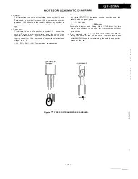
NOTES ON SCHEMATIC DIAGRAM

T Y P E S   O F   T R A N S I S T O R   A N D   L E D

REPLACEMENT PARTS LIST . . . . .


Page


2

. . . . . . . .

2

3

. . . . . . . .

4


. . . . . . . .

5

. . . . . .

6 - 8

. . . . .

8

. . . . . 9, 

. . .

. . . . .
. . . . . .

15

. . . . . . .

. . . . . 1 6 - 1 9


Summary of Contents for GF-320A

Page 1: ...d only parts identical to those specified be used INDEX TO CONTENTS SPECIFICATIONS STRINGING OF DIAL CORD NAMES OF PARTS DISASSEMBLY BLOCK DIAGRAM CIRCUIT ADJUSTMENT MECHANICAL ADJUSTMENT EXPLODED VIEW SCHEMATIC DIAGRAM WIRING SIDE OF P W BOARD NOTES ON SCHEMATIC DIAGRAM TYPES OF TRANSISTOR AND LED REPLACEMENT PARTS LIST r I 1 I Page 2 2 3 4 5 6 8 8 9 IO II 12 13 14 15 15 1 6 1 9 SHARP CORPORATION...

Page 2: ...e TAPE RECORDER Tape Frequency response Signal noise ratio Wow and flutter SPEAKER Speakers Impedance Maximum power handling capacity I FM 87 6 108 MHz AM 526 5 1 606 5 kHz Compact cassette tape 100 Hz 10 000 Hz 36 dB 0 2 WRMS 10 cm 4 woofer x 2 Horn type tweeter x 2 4 ohms 5 W maximum batteries Specifications for this model are subject to change without prior notice STRINGING OF DIAL CORD Dial Co...

Page 3: ... Record Button 10 Play Button 11 Rewind Button 12 Fast Forward Button 13 Stop Eject Button 14 Pause Button 15 Graphic Equalizer Control 16 Speaker Cord Holder 17 Speaker Release Lever 18 External Microphone Jack 19 External Speaker Terminals 20 Telescopic Rod Antenna 2 1 Battery Compartment 22 AC Power Supply Socket 1 234 56 7 8 7 18 19 20 21 22 17 16 Figure 3 1 Figure 3 2 3 ...

Page 4: ...ads where they were before disassembling 4 Take sufficient care on static electricity of integrated cir cuits and other circuits when servicing STEP REMOVAL PROCEDURE FIGURE Main body section I Front Cabinet 1 Battery comparment lid Atxl 2 Open the cassette holder B 3 Screw C x5 4 l Mechanism Block 1 Screw 01x2 2 Socket tE x2 3 Tip F x2 Main P W Board o d a k l tbr G xl sprmg Hlxl 4 2 4 3 Speaker ...

Page 5: ...SWIOI A F FUNCTION SELECTOR SWITCH SWIOZ A J RECORD PLAYBACK SWITCH Figure 5 BLOCK DIAGRAM 5 ...

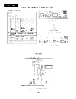
Page 6: ... E R JUST REMARKS SETTING MENT 1 IF 455 kHz High T3 Adjust for frequency best IF cu we 2 510 kliz Lowest L8 Band frequency Adjust for coverage maximal 3 1 650 Highest TC8 output kHz frequency Repeat steps 2 and 3 until no further improvement can Figure 6 1 AM IF 455 kHz A Figure 6 2 AM IF CURVE Signal Generator Test Loop Bar Antenna Figure 6 3 AM RF Figure 6 4 ADJUSTMENT POINTS 6 ...

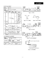
Page 7: ...l I Unit be made Band frequency coverage 109 MHz Highest TC2 maximal output 1 frequency Repeat steps 4 and 5 until no further improvement can be made 88 MHz 88MHz L2 Adjust for Trackmg maximal 108 MHz 108 MHz TCl output Repeat steps 7 and 8 until no further improvement can be made 5 Dummy See Figure 7 6 6 7 Figure 74 FM RF Electronic B FM Signal Generator Rod Antenna I 9 7 VCO FREQUENCY ADJUSTMENT...

Page 8: ...rd TW 223 1 Rewind TW 223 1 Azimuth Tape speed 1 ADJUSTMENT POINTS I Test Tape MTT 113C Azimuth adjusting screw External Oscilloscope Test Tape MTT 118 Head F i g u r e 8 1 P L A Y B A C K A M P L I F I E R S E N S I T I V I T Y MECHANICAL ADJUSTMENT Ruba3Ks CHECK More than 140 g Play 30 60 g m Fast forward 55 IlOgcm Rewind 55 1lOgcm Sine waveform attains the maximum 3 000 90 Hz Test 1 MTT 1 E V E...

Page 9: ...1 I 2 I 3 I 4 I 5 I 6 63 I 44 49 57x3 c v5 73 60mm 103 ...

Page 10: ... 1 203 204 LEFT 205fRIGHTl ii 214x6 605 GRAPHIC EOALIZER PWB B T 238 21 Figure 10 CABINET EXPLODED VIEW 10 _ _ _ __ __ _ I__ III 2 _ _ I ...

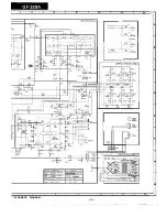
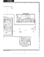
Page 11: ...0103 290655 E RIPPLE FILTER l NOTES ON SCHEMATIC DIAGRAM can be found on page 15 1 I 2 I 3 I 4 I 5 I 6 Figure 11 SCM ll ...

Page 12: ...I M A I N PWB Al I l c44 Ill25 P701 0702 ZSCl815 G R GRAPHIC EQUALIZEF a703 0704 X 2 G R J III I I J POWER SUPPLY PWR A I 7 I 8 I 8 I 10 I 11 I 12 1 SCHEMATIC DIAGRAM 12 ...

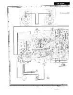
Page 13: ...I 1 I 2 1 3 I 4 I 5 I 6 Figure 13 WlRiNG Sir ...

Page 14: ...7 I 8 I 9 1 IO I I I I I2 GRAPHIC EQUALIZER PW B B I 7 I 8 I 9 I IO I I I I I2 3 SIDE OF P W BOARD I4 ...

Page 15: ...the expression capacitance withstand voltage is used CH TH RH UJ Temperature compensation 2SC1815 GR 250655 E E C 8 000 0 l The indicated voltage in each section is the one measured by Digital Multimeter between such a section and the chassis with no signal given AM mode Marking except for FM mode Schematic diagram and Wiring Side of P W Board for this model are subject to change for improvement w...

Page 16: ... 1 Silicon 1 SS133 VHERDSRl JB2 1 Zener 5 1 V RD5 1 JB2 VHDS5566G 1 Silicon S5566G VHDS5566G 1 Silicon S5566G VHDS5566G 1 Silicon S5566G VHDS5566G 1 Silicon S5566G AA AA AA AA AA AA AC AC AB AA AA AB AB AB AB COILS RCiLA0652AFZZ FM Band Pass Filter 92LCdiLR 197A FM RF 92LCijiL 158A FM Oscillator RCilAO796AFZZ AM Bar Antenna 92LCbiL 200A AM Oscillator TRANSFORMERS AD AA AA AH AC 92LiFT 258A FM IF 9...

Page 17: ...PAl HFl03Z 0 0 1 pF 5 0 V VCKZPAl HF103Z 0 0 1 uF 5 0 V AA AA AA AA AA AA AA AA AA AA AA AA AA AA AA AA A A AB AA A A AA AA A A AA AA A A AA AA AA AA AA A A AA AA AA AA AA AA AA AA AA AB AB AA AA AA A A AA IiI REF NO PART NO DESCRIPTION CODE c701 VCTYMFl EX822K 0 0 0 8 2 pF 2 5 V AA C702 VCTYMFl EX822K 0 0 0 8 2 pF 2 5 V A A c707 VCKYMFl HB102K 0 001 PF 5 0 V A A C708 V C K Y M F l HB102K 0 001 PF...

Page 18: ...ver Play Button AC 6 94R18210130 Lever Rewind Button AC 7 94R18210131 Lever Fast Forward Button AC 8 94R18210132 Lever Stop Button AC 9 94R182101503 Lever Ass y Pause Button AD 10 94R18210168 11 94R18210115 12 94R18210116 13 94Rl8210134 14 94Rl8210123 15 94Rl8210119 16 94R18210124 17 94R18210150 18 94R18210138 19 94R18210122 2 0 94R18210162 21 94R18210121 2 2 94Rl8210113 2 4 94Rt 8290110 2 5 94Rl8...

Page 19: ...nt Lid R Battery Compartment Lid P Battery Compartment Lid Y Battery Compartment Lid BL Dial Pointer Handle BK AC AD AD AD AD AD AB AE 19 REF NO PART NO DESCRIPTION CODE 210 210 210 210 211 212 213 214 215 216 217 218 219 220 221 222 223 224 226 227 228 229 230 231 232 233 234 238 238 238 238 238 601 602 603 604 605 606 92LHNDL571 A RD Handle R AE 92LHNDl572A PK Handle P AE 92LHNDL573A YW Handle Y...

Page 20: ...S H A R P A8603 749NS IS M Writer and Editor Quality Reliability Control Center of Audio Systems Group Sharp Corp Printed in Japan ...

Reviews: