background image

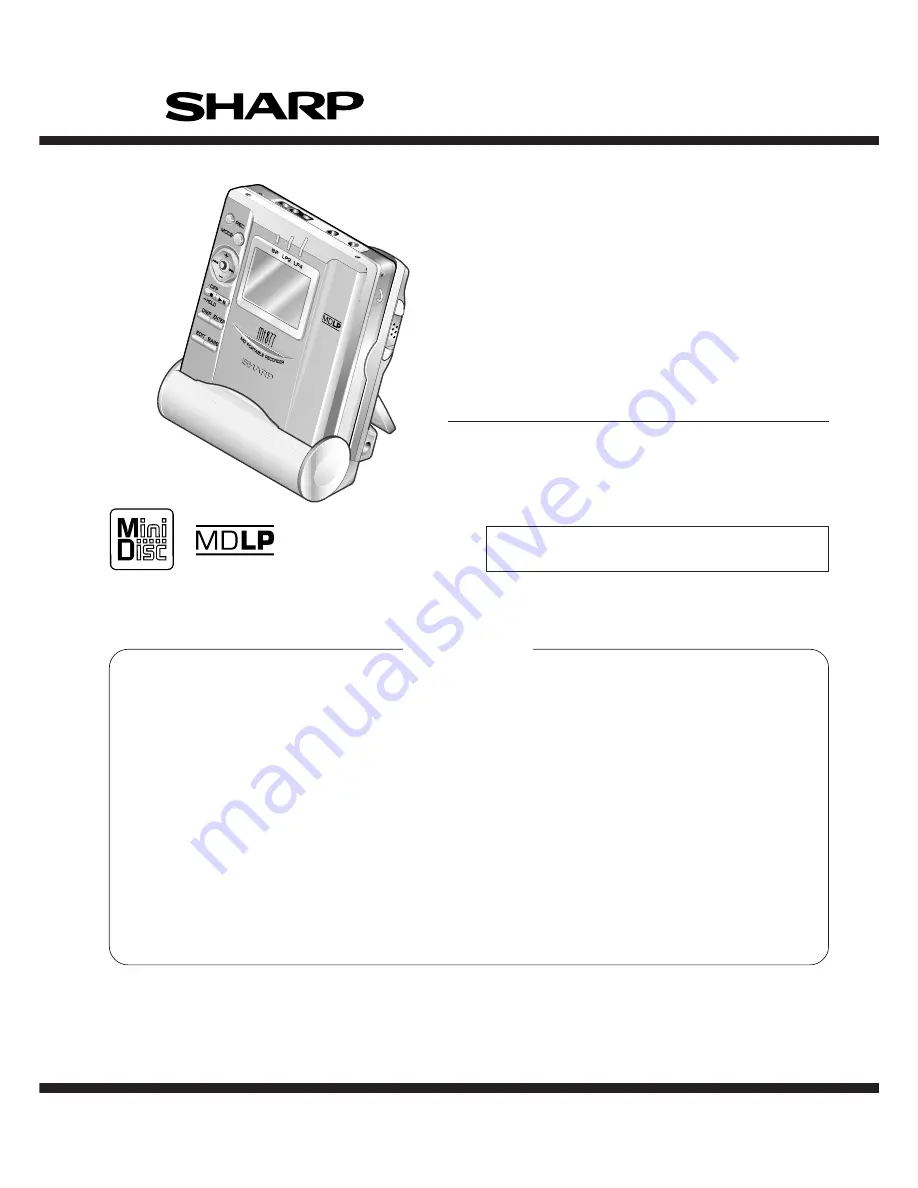
MD-MT877/MD-MT877C

CONTENTS

Page

SPECIFICATIONS .................................................................................................................................................................  2
NAMES OF PARTS ...............................................................................................................................................................  3
OPERATION MANUAL ..........................................................................................................................................................  5
DISASSEMBLY ....................................................................................................................................................................  10
REMOVING AND REINSTALLING THE MAIN PARTS .......................................................................................................  11
ADJUSTMENT ...................................................................................................................................................................... 12
NOTES ON SCHEMATIC DIAGRAM ..................................................................................................................................  28
TYPES OF TRANSISTOR AND DIODE ..............................................................................................................................  28
BLOCK DIAGRAM ...............................................................................................................................................................  29
SCHEMATIC DIAGRAM ......................................................................................................................................................  30
WIRING SIDE OF P.W.BOARD ...........................................................................................................................................  32
VOLTAGE ............................................................................................................................................................................  36
WAVEFORMS OF MD CIRCUIT .........................................................................................................................................  37
TROUBLESHOOTING .........................................................................................................................................................  38
FUNCTION TABLE OF IC ....................................................................................................................................................  41
PARTS GUIDE/EXPLODED VIEW
PACKING OF THE SET (MD-MT877(S) FOR U.S.A. ONLY)

SERVICE MANUAL

SHARP  CORPORATION

No. S3118MDMT877/

This document has been published to be used
for after sales service only.
The contents are subject to change without notice.

MD-MT877(S)

MODEL

MD-MT877C(S)

• In the interests of user-safety the set should be restored to its

original condition and only parts identical to those specified be
used.

PORTABLE MINIDISC RECORDER

Summary of Contents for MD-MT877

Page 1: ...VEFORMS OF MD CIRCUIT 37 TROUBLESHOOTING 38 FUNCTION TABLE OF IC 41 PARTS GUIDE EXPLODED VIEW PACKING OF THE SET MD MT877 S FOR U S A ONLY SERVICE MANUAL SHARP CORPORATION No S3118MDMT877 This document has been published to be used for after sales service only The contents are subject to change without notice MD MT877 S MODEL MD MT877C S In the interests of user safety the set should be restored t...

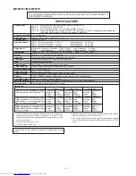
Page 2: ...ing 24 bit computed type Recording method Magnetic modulation overwrite method Sampling frequency 44 1 kHz 32 kHz and 48 kHz signals are converted to 44 1 kHz and then recorded Wow and flutter Unmeasurable less than 0 001 W peak Battery life The above values are the standard values when the unit is operated hori zontally and charged at an ambient temperature of 77 F 25 C The operable duration with...

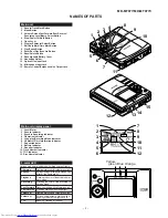
Page 3: ...ormation Indicator 7 Repeat Indicator 8 Battery Indicator 9 Random Indicator 10 Track Number Indicator 11 TOC Indicator 12 Disc Name Indicator Main unit display panel 3 color LED Various modes are indicated with three colors of lights Charging Lighting starting with yellow green light Refresh Extinguishing starting with orange light after all the lights are lit Playback Flashing the color of the a...

Page 4: ...Remote control display panel Remote control unit 1 Earphones Jack 2 Fast Forward Fast Reverse Button 3 Display Button 4 Play Mode Button 5 Sound Track Mark Button 6 Stop Power Off Button 7 Play Pause Button 8 Volume Button 9 Hold Switch 1 Remote Control Holder You can hang the remote control on it 2 Lock Detector 3 Hook For Fixing The Main Unit 4 Charge Operation Switch 5 Stand 6 AC Adaptor Connec...

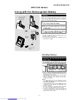
Page 5: ...hown by the battery indicator during operation When the battery is completely discharged the battery indicator will flash Recharge the battery or replace the alkaline battery with a new one When the battery has run completely out BATT EMPTY LoBATT will appear Then the power will be discon nected automatically Notes If you use the battery which you stopped charging half way may appear It does not m...

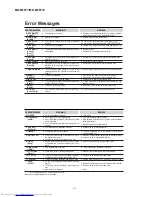
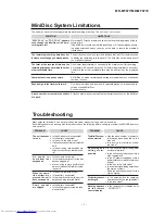
Page 6: ... where you pur chased the unit Return the HOLD switch to its original position Turn off the power and remove the MiniDisc Error Messages continued ERROR MESSAGES NO DISC NO SIGNAL noSIG PLAY MD PLAYmd POWER PROTECTED SORRY Sorry TEMP OVER TEMP TOC FORM Tform TOC FULL Tr Protect DISC DISC MEANING A disc has not been loaded Poor connection of the digital cable No output signal comes out from the con...

Page 7: ... problems can be resolved by the owner without calling a service technician If something seems to be wrong with this product check the following before calling your authorized SHARP dealer or service center The unit does not turn on No sound is heard from the earphones When the opera tion buttons are pressed the unit does not respond Some sounds are skipped Is the AC adaptor disconnected Is the ba...

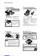
Page 8: ...dor de CA 2 Connect the AC adaptor Conecte el adaptador de CA RELEASE LOCK To the DC IN 5V jack A la toma DC IN 5V AC 120V 60 Hz 120V CA 60Hz Insert securely all the way in Insértelo con seguridad a fondo To an AC outlet A un tomacorriente de CA LINE OUT LEFT RIGHT OPTICAL LINE IN White To Left Blanco A la izquierda Red To Right Rojo A la derecha 3 Connection Conexión To a stereo system with LINE ...

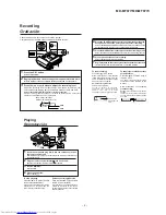
Page 9: ...que desee iniciar la grabación 5 Press the MODE button repeatedly to select the recording mode Pulse repetidamente el botón MODE para seleccionar el modo de grabación 6 Press the button to start recording Pulse el botón para iniciar la grabación 7 Begin playback on the stereo system the output will be recorded Inicie la reproducción del sistema estéreo y se grabará la salida To update the recorded...

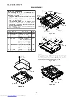
Page 10: ...s to fix the cabinet and the mechanism unit The use of the screws with length other than specified may cause contact with the mechanism unit resulting in malfunction 3 When repairing pay close attention so not to damage the IC from static electricity REMOVAL PROCEDURE STEP FIGURE Figure 10 1 Figure 10 2 Figure 10 4 Caution Carefully handle the main PWB and flexible PWB After removing the flexible ...

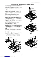
Page 11: ...d wire 2 Remove the screw B2 x 1 pc and remove the lift motor Note Take care so that the motor gear is not damaged If the gear is damaged noise is caused How to remove the sled motor See Fig 11 3 1 Remove the stop washer C1 x 1 pc and remove the drive gear C2 x 1 pc 2 Remove the screws C3 x 2 pcs 3 Remove the solder joints C4 x 3 of flexible PWB and remove the sled motor Note Take care so that the...

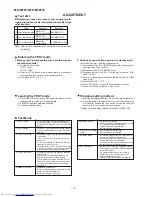
Page 12: ...he displayed adjustment value perform preliminary manual adjustment Error rate indication jump test 6 MANUAL 2 Mode Temperature is displayed Seeing the displayed adjustment value perform ATT attenuator manual adjustment Continuous playback is performed error rate display jump test 7 ERROR INFORMATION Error information is displayed Mode Error information is initialized 8 NORMAL Mode The mode is cha...

Page 13: ...ton is pressed in B ATT set state the mode is changed to the continuous playback mode As for operation during continuous playback refer to TEST PLAY mode explanation 5 TEST PLAY Mode When the STOP button is pressed while the TEST PLAY menu appears or in TEST PLAY or continuous playback mode the mode changes to the TEST mode stop state When the PLAY button is pressed while the TEST PLAY menu appear...

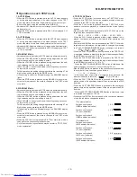
Page 14: ...retrial 16h C IN detection time over 17h A B E F and TCRSO offset measurement value out of tolerable range 21h Focus retraction completion allowable time over 23h Track search completion allowable time over 32h P TOC read failure 42h U TOC read failure 44h U TOC write data write disabled read check error 45h U TOC write test failure 52h SD write data write disabled 72h EEPROM data read check sum e...

Page 15: ... VOLUME or VOLUME button 9 Set the temperature reference Refer to the Tempera ture reference setting method 10 Set according to the EEPROM DATA LIST 11 Press the STOP button T E S T 12 Press the STOP button 13 After data is written in EEPROM turn off power 2 Temperature reference setting method 1 Measurement calculation and setting procedure 1 Set the TEST mode 2 Start the EEPROM mode Temp menu Bu...

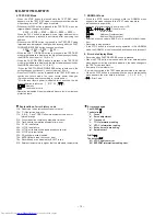
Page 16: ... 0DH TDo _ 67H TDt _ 34H SCo _ 00H SCt _ 3AH SCm _ 48H CLp _ 24H CLr _ 30H JPI _ 0EH K10 _ 65H THP _ 02H THG _ 02H TOP _ 00H TOG _ F4H T1P _ 20H Item display Set values Tracking setting SPG _ 30H SPi _ 9AH SPm _ 62H SPo _ 4FH PGM _ E0H SP1 _ 10H SP2 _ 60H SP3 _ F2H SP4 _ F2H SP5 _ 10H Sp2 _ 60H Sp5 _ 10H SD1 _ 7FH SD2 _ 7FH SPK _ EBH MPG _ 28H SPL _ 60H SPW _ 0FH SPB _ 66H SRi _ C0H SRm _ 9AH SRo ...

Page 17: ...H GQ1 _ 98H GQ2 _ 84H GSG _ 11H EQP _ 00H Item display Set values CT0 _ 02H CT1 _ 01H CT2 _ 30H CT3 _ 20H CT4 _ D0H CT5 _ 4BH CT6 _ 18H RC0 _ C0H RC1 _ FEH SYC _ A6H PWL _ 54H DR1 _ 24H DR2 _ 22H IN1 _ 17H IN2 _ 11H INH _ 00H DRH _ 64H PLE _ A6H RCE _ 94H ELT _ A0H X2T _ C0H SDF _ 1FH CHV _ 50H DRS _ 5AH DUP _ 00H RFL _ D0H CG1 _ 66H FB0 _ FCH RST _ 00H R20 _ 80H R21 _ 20H R40 _ BFH R41 _ 02H FBL ...

Page 18: ...stment Pickup position initialisation EEPROM contents renewal STOP Indication after the start During the spare style automatic adjustment During the focus balance adjustment During the adjustment that ATT is automatic Normality completion Adjustment completion Continuance is regenerating It confirms that an address proceeds PLAY PLAY A U T O 1 Do the following when replacing the mechanism the pick...

Page 19: ...djustment error Preadjustment error adjustment value output During preautomatic adjustment Adjustment error Normal end Preadjustment normal end adjustment value output During ATT automatic adjustment PLAY PLAY A U T O 1 Servo Preautomatic Adjustment A D J O K A D J N G A T 2 A T 1 When the STOP button is pressed in specific menu the TEST MODE STOP state is set Move the pickup lens manually to the ...

Page 20: ...ayback When the STOP button is pressed in specific menu the TEST MODE STOP state is set In the start address set state the start address changes as follows when the DISP button is pressed 0 0 3 2 H initial value 0 3 C 0 H 0 7 0 0 H 0 8 A 0 H A d 0 0 3 2 A d 0 3 C 0 DISP DISP A d 0 7 0 0 DISP DISP A d 0 8 A 0 In the start address setting state the start address change digit changes when the P MODE ...

Page 21: ...h AUTO2 Practice finish YES YES E r A D J AUTO2 Practice No error A D J N G NO NO YES NO Enter the EEPROM setting mode and press the FAST FORWARD button Change the MSL setting value from 00 to 08 by using CTRL_ control setting menu If the MSL remains in 00 no signal is recorded In the continuous playback state the number of jump lines changes as follows shown the BASS button is pressed 1 initial v...

Page 22: ...WN SKIPUP SKIPDOWN Pit section EF signal level measurement LPFEFO Measurement value Groove section EF signal level measurement LPFEFO Measurement value TCRS signal level measurement TCRSMIO Measurement value A ATT focus initial setting ATT setting B ATT focus initial setting ATT setting TCRS signal offset TCRSO measurement Measurement value a b S A SKIPUP SKIPDOWN S B SKIPUP SKIPDOWN T H SKIPUP SK...

Page 23: ... menu Temperature code indication Temperature code Laser ON play power Pit section E ATT tracking setting ATT setting Pit section F ATT tracking setting ATT setting High reflection A ATT focus setting Low reflection A ATT focus setting ATT setting TCRS ATT setting ATT setting Groove section E ATT tracking setting ATT setting Groove section F ATT tracking setting ATT setting Low reflection A ATT fo...

Page 24: ... the laser ON state with no disc or the lid open laser power changes as follows Playback power Record power Maximum power BASS BASS BASS L O N P L O N R L O N M EFMIO measurement value indication REPEAT 1 Mark lighting LPFFINO measurement value indication 1 Mark lighting Pit section F ATT tracking setting Groove section F ATT tracking setting EFMIO measurement value indication REPEAT 1 Mark lighti...

Page 25: ...T H SKIPUP SKIPDOWN e f SKIPUP SKIPDOWN T C SKIPUP SKIPDOWN a b SKIPUP SKIPDOWN P C H SKIPUP SKIPDOWN G C H SKIPUP SKIPDOWN S A SKIPUP SKIPDOWN SKIPUP SKIPDOWN When the STOP button is pressed in specific menu the TEST MODE STOP state is set In the specific setting display state the setting change digit changes when the P MODE button is pressed In the case of the setup value two digits 1st digit in...

Page 26: ...n the specific state the setting changes in the range of 0h to Fh when the VOLUME button is pressed P MODE P MODE Error history indication menu Error history 0 indication Error code Error history 1 indication Error code Error history 2 indication Error code Error history 3 indication Error code Error history 4 indication Error code Error history 5 indication Error code Error history 6 indication E...

Page 27: ...ion is performed in the specific state the menu changes to TEMP SETTING menu When the P MODE button is pressed in each state the set digit is changed 1st digit initial value 2nd digit When the STOP button is pressed in specific menu the TEST MODE STOP state is set When the DISP button operation is performed in the specific state the menu changes to TEMP SETTING menu In the specific setting display...

Page 28: ...means pico farad and the unit of the capacitor without such a symbol is microfarad As to electrolytic capacitor the expression capacitance withstand voltage is used CH TH RH UJ Temperature compensation ML Mylar type The indicated voltage in each section is the one measured by Digital Multimeter between such a section and the chas sis with no signal given Parts marked with are important for maintai...

Page 29: ... 10 12 55 60 39 41 43 27 31 40 45 29 40 37 26 30 32 37 39 46 2 5 7 11 14 23 6 7 66 74 9 2 3 15 4 20 17 6 19 12 10 6 24 L CH 22 R CH 17 Q721 1 2 1 3 17 27 52 64 1 3 2 5 6 7 96 99 40 47 48 81 91 92 31 33 49 72 2 5 17 22 24 25 57 58 5 2 8 3 1 12 2 7V 82 84 86 89 100 4 7 5 6 SW401 EJECT SW901 DISC PROTECT 68 12 53 54 62 73 8 PLAYBACK SIGNAL RECORD SIGNAL B M M M 2 7V 1 11 36 38 73 74 93 R CH L CH 2 R ...

Page 30: ...A2 SPDRR SPDRF SLDRR VCC A10 VCC A3 A2 A1 A0 RAS WE I O2 I O1 GND I O4 I O3 CAS OE A9 GND A8 A7 A6 A5 A4 9 8 7 6 5 4 3 2 1 SYD7 SYD4 SYD3 SYRS SYRD SYD6 SYD5 SYD2 SYD1 SYD0 SYWR RCAULT INPGCK MCPGIN INPGIN RFPCNT TP417 TP416 BEEP SGAIN OPICGA TP415 PBMUTE AUSCLK AUDATA DSPSCK DSPSTB DSPDAT CHGCNT CIN DISCPR SPIN DISC DINT FP31 FP32 TP412 LDVAR TEMP RKEY STDCK HKEY2 HKEY1 PLVBAT PLVDCI FP66 TP406 _...

Page 31: ...1K TP404 C401 0 1 D432 1SS372 R831 180K C840 220 4 TP464 R731 47K R733 47K R732 47K TP462 CN451 C202 47 6 3 L202 10µH TP460 TP453 TP452 TP459 TP458 TP457 TP455 TP454 TP456 TP451 TP461 D801 RB521S30 R495 1K R496 22 C493 0 47 Q493 2SA1832 GR F841 0 4A DC60V TP841 R828 2 2K R802 100K Q802 FDN339N R256 100K R257 1M R710 47 R822 100K Q821 HN1C01FU R821 2 2K C253 0 01 R259 2 2K R807 100K Q806 HN1C01FU R...

Page 32: ...3 C837 IC873 C844 C848 R841 R408 R406 R405 R407 R766 R765 C765 C766 IC703 R767 R768 D491 C492 D496 D495 D492 R492 L491 D494 C491 IC701 C722 R729 R907 R908 C721 IC771 C774 C503 C511 CN451 C753 IC404 C605 C905 R461 R463 R462 R904 C906 C910 C909 R909 Q442 Q443 R441 R442 C500 TP105A FP67 R445 R903 C907 R404 C454 R464 R732 R733 R731 C760 R757 R712 C734 C733 R758 R754 R720 R719 R711 C758 C754 C902 R761 ...

Page 33: ...L821 TP405 L601 L602 L603 TP211 C821 R717 C822 C600 C869 C771 TP711 J702 MIC IN TP412 TP713 TP714 R701 TP712 TP708 R702 TP704 C702 TP487 J701 OPTICAL LINE IN C701 TP705 C851 C852 TP806 C859 TP703 TP701 TP351 C840 L851 TP452 R710 C715 R718 D851 IC851 D852 C858 TP352 TP702 TP707 CK201 TP706 TP201 TP655 TP205 TP654 TP652 TP653 TP651 CK203 TP209 TP210 TP407 TP409 TP408 TP660 TP658 TP659 TP657 TP661 TP...

Page 34: ... LCD ASS Y P35 7 H SWA13 OPEN CLOSE CA02 RA06 CA01 RA08 RA07 RA05 LEDA03 LEDA02 LEDA04 QA01 RA16 RA15 SWA01 RECORD SWA09 MODE SWA07 VOLUME SWA10 FAST REVERSE SWA11 FAST FORWARD SWA06 VOLUME SWA02 PLAY SWA05 DISPLAY SWA12 ENTER SWA04 EDIT SWA03 BASS RA04 RA03 RA02 RA01 RA14 RA12 RA13 CNA01 SWA08 STOP 1 7 14 1 CN451 TO MAIN PWB P32 2 F FLEXIBLE PWB LCD KEY PWB B BOTTOM VIEW ...

Page 35: ...igure 35 WIRING SIDE OF P W BOARD 4 4 TO MAIN PWB P32 2 D M902 SLED MOTOR M903 LIFT MOTOR MECHANISM FLEXIBLE PWB 5 M901 SPINDLE MOTOR MAGNETIC HEAD 3 CN601 TO MAIN PWB P32 2 B OPTICAL PICKUP 4 TO LCD KEY PWB P34 4 F LCD ASS Y 217 CN101 CNA01 ...

Page 36: ... 9 10 11 12 13 14 3 1 2 4 5 3 1 2 4 5 6 7 8 3 1 2 4 3 37 38 40 41 42 43 44 45 46 47 48 49 50 51 52 53 54 55 56 39 1 2 4 5 6 7 8 9 10 11 12 13 14 15 16 17 18 19 20 21 22 23 24 25 26 27 28 29 30 31 32 33 34 35 36 3 1 2 4 5 6 7 8 9 10 11 12 13 14 15 16 17 18 19 20 21 22 23 24 3 1 2 4 5 3 0 79 V 2 49 V 1 3 V 0 V 2 49 V 1 25 V 1 25 V 1 25 V 1 25 V 1 25 V 1 25 V 1 25 V 1 V 1 55 V 0 V 0 V 1 24 V 0 V 0 V ...

Page 37: ... Smoothiing OFF BW FULL CH1 0 000V CH2 0 00V Main 1K Zoom 1K CH3 0 00V CH4 0 00V Trigger Mode AUTO Type EDGE CH1 Detay 0 0ns Hold OFF MINIMUM T TP201 EFMMON Stopped CH1 2V DC 10 1 500ms div 500ms div 1 MORM 200MS s 9 1994 12 15 08 57 26 Filter Offset Record Length Smoothiing OFF BW FULL CH1 0 00V CH2 0 00V Main 10K Zoom 10K CH3 0 000V CH4 0 0V Trigger Mode NORMAL Type EDGE CH1 Detay 0 0ns Hold OFF...

Page 38: ...n the remote control button or main unit button is pressed No Perform the check stated in item Power is not turned on when the button is pressed Perform the check stated in item Abnormal display No Yes Does the display operate normally Is playback state set Yes Perform the check stated in item Playback state cannot be set No Is audio output normal Yes Perform the check stated in item Audio playbac...

Page 39: ...eriphery of IC401 Audio playback clrcult Is audio waveform output from IC501 pins 15 and 16 Check headphones jack and periphery of headphone In the normal playback mode LCD play time display functions but no audio is heard Check for pattern breakage of flexible PWB check for defects of display microcomputer replace the display unit The spindle motor fails to run Does the head move No Does the wave...

Page 40: ...1 varies with the recording VOLUME button operation Check whether the soldering of IC701 is poor No Check whether the audio signal line between IC701 and J701 is defective Is audio waveform observed on the pins 10 and 12 of IC701 Yes Check whether input waveform is observed on the pins 5 and 6 of IC701 Yes Check voltage of pins 57 and 58 of IC201 pins 2 3 6 and 7 of IC651 pins 4 and 5 of CN601 Che...

Page 41: ...SPSTB Output Unit display strobe output 33 SCK2 DSPSCK Output Unit indication data clock output 34 P10 PBOPON Output Audio IC output stage control output 35 P11 P11 Output Reserve 36 P12 TCLKA CIN Input Track cross signal focus drive detection 37 TCLKB SPIN Input Spindle motor FG pulse detection input 38 IRQ0 _DINT Input System LSI interruption 39 P15 DISCPR Input Disc record inhibition switch inp...

Page 42: ...ontrol Blue 81 P35 _STOP Input Unit stop button control detection input 82 P36 LEDCTR Output LED lighting control Orange 83 P77 DCNT Output Mechanism driver enable output 84 P76 BATON Output Battery power supply line ON OFF 85 P75 LDON Output P C laser ON OFF control output 86 P74 PBLAT Output Audio PC data clock output 87 P73 PCNT3 Output _DC IN input control output 88 P72 DCON Output DC power su...

Page 43: ...RT0 DAPON Output D A converter operation control output H Operation ON 81 EXPORT1 ADPON Output A D converter operation control output H Operation ON Pin No Function Port Name Terminal Name Input Output Remarks H H Normal mode H L No adjustment mode L H Test mode L L Settings prohibited TEST1 Details 1 List of TEST port settings H H fs 32K ON H L fs 48K ON L H OFF L L fs 44 1K ON EMPH1 EMPH0 Detail...

Page 44: ... 44 MD MT877 MD MT877C M E M O ...

Page 45: ...lindrical type without lead wire VC MN Cylindrical type without lead wire VC TV Square type without lead wire VC TQ Square type without lead wire VC CY Square type without lead wire VC CZ Square type without lead wire VC J The 13th character represents capacity difference J 5 K 10 M 20 N 30 C 0 25 pF D 0 5 pF Z 80 20 If there are no indications for the electrolytic capacitors error is 20 Resistors...

Page 46: ...VHDHRB0103B 1 J AC Silicon HRB0103B D851 852 VHDF10J2E 1 J AC Silicon F10J2E D861 862 VHDF10J2E 1 J AC Silicon F10J2E LEDA02 VHPTLGU1008 1 J AE LED Yellow green TLGU1008 LEDA03 VHPCL190HBX 1 J AR LED Blue CL190HBX LEDA04 VHPTLOU1008 1 J AE LED Orange TLOU1008 COILS L100 VPBNN100K0000 J AC 10 µH L103 RCILC0353AFZZ J AB Tip Solid Induction 100mA L171 RCILC0356AFZZ J AC 10 µH L202 VPBNN100K0000 J AC ...

Page 47: ... R200 VRS CZ1JB104D J AA 100 kohm 1 16W R204 VRS CZ1JB102J J AB 1 kohm 1 16W R205 VRS CZ1JB273D J AA 27 kohms 1 16W R206 VRS CZ1JB104D J AA 100 kohm 1 16W R207 VRS CZ1JB681J J AB 680 ohms 1 16W R222 VRS CZ1JB105J J AB 1 Mohm 1 16W R251 VRS CZ1JB220J J AB 22 ohms 1 16W R252 VRS CZ1JB564J J AA 560 kohms 1 16W R253 VRS CZ1JB333J J AB 33 kohms 1 16W R254 VRS CZ1JB105J J AB 1 Mohm 1 16W R255 VRS CZ1JB5...

Page 48: ... Key Type Fast Reverse SWA11 QSW K0237AFZZ J AC Switch Key Type Fast Forward SWA12 QSW K0237AFZZ J AC Switch Key Type Enter SWA13 QSW M0009AWZZ J AE Switch Push Type Open Close MD MECHANISM PARTS 1 NGERH0125AWZZ J AB Wheel Drive 2 NSFTD0007AWZZ J AL Screw Drive 3 RCILH0003AWM1 J AT Magnetic Head Ass y 1 4 RCTRH8210AFZZ J BM Optical Pickup 5 QPWBH0010AWZZ J AH Mechanism Flexible PWB 6 LHLDX3008AWM2...

Page 49: ... Operation Manual MD MT877 S TINSZ0640AWZZ J AC Quick Guide MD MT877 S TLABZ0695AWZZ J AA Label Caution Battery Case UBAGC0005AWZZ J AD Battery Carrying Case UBAGC0006AWSA J AH Carrying Case UBATM0006AWSA J AY Battery P W B ASSEMBLY Not Replacement Item PWB A 92LPWB3664MDSS J Main PWB B 92LPWB3532KEYS J LCD Key OTHER SERVICE PARTS UDSKM0001AFZZ J AZ Recording Mini Disc 88GMMD 110 J BV High Reflect...

Page 50: ...MD MT877 MD MT877C A B C D E F G H 1 2 3 4 5 6 Figure 5 MD MECHANISM EXPLODED VIEW 5 5 3 10 4 2 1 17 6 9 7 M901 12 15 M902 M903 11 501 16 501x2 502 506x3 504x2 505 503 507 14 508 13 ...

Page 51: ...PEN OPEN OPEN OPEN LCD PWB MD MECHANISM 223x2 224x2 225x4 MAIN PWB 603x2 603x2 212x3 604x4 603x2 205 201 207 210 209 208 212 212 214 215 216 217 231 230 203 218 219 220 221 204 601 226 602 227 601 235 237 236 232 601 603 603 603 228 229 236 202 233 234 213 239x3 240 603 238 241 242 ...

Page 52: ...MD MT877 MD MT877C A B C D E F G H 1 2 3 4 5 6 7 Figure 7 BATTERY CHARGER EXPLODED VIEW 22 1 22 5x2 22 4 22 3 22 6 22 5x2 22 2 22 7 22 7 22 22 9 22 8 ...

Page 53: ...ng Case Earphones Battery Case AC Adaptor Packing Case SPAKC1155AWZZ Connecting Cord RCA Type Battery Battery Carrying Case Remote Control Label Caution Battey Charger AC Adaptor Pad SPAKZ0630AWZZ Sheet Bubble SPAKZ0692AWZZ Packing Add SPAKA0284AWZZ Quick Guide Connecting Cord Optical Type Polyethylene Bag Battey Charger SSAKA0009AWZZ Not Replacement Item ...

Page 54: ... M E M O MD MT877 MD MT877C 9 ...

Page 55: ... M E M O MD MT877 MD MT877C 10 ...

Page 56: ...retrieval system or transmitted in any form or by any means electronic mechanical photocopying recording or otherwise without prior written permission of the publisher A0103 1267DS HA M SC LAG SL SHARP CORPORATION Communication Systems Group Quality Reliability Control Center Higashihiroshima Hiroshima 739 0192 Japan Printed in Japan ...

Reviews: